Eureka AIR delivers breakthrough ideas for toughest innovation challenges, trusted by R&D personnel around the world.

Seal ring and centrifugal wheel sealing structure suitable for low-temperature environment

A technology of sealing structure and low-temperature environment, which is applied to components of pumping devices for elastic fluids, non-variable pumps, machines/engines, etc., and can solve the variability of the overall stiffness of non-metallic sealing rings, centrifugal wheel seals Problems such as convex edge eccentric wear and reduced sealing effect can be achieved to achieve the effect of good sealing structure stability, enhanced overall rigidity and small gap

Inactive Publication Date: 2020-05-12
XIAN AEROSPACE PROPULSION INST
View PDF7 Cites 2 Cited by
  • Summary
  • Abstract
  • Description
  • Claims
  • Application Information

AI Technical Summary

Problems solved by technology

[0007] The main purpose of the present invention is to solve the problem that the metal sealing ring and the sealing flange of the centrifugal wheel are prone to friction and explosion in the medium and low temperature environment of the prior art, the overall rigidity of the non-metallic sealing ring is poor and variable, and the non-metallic inner core in the sandwich-type sealing ring is integrated. The processing is easy to deform, and it is easy to be eccentrically worn with the centrifugal wheel sealing flange, which leads to the technical problem of reducing the sealing effect. A sealing ring and a centrifugal wheel sealing structure suitable for low temperature environment are provided.

Method used


Image

  • Seal ring and centrifugal wheel sealing structure suitable for low-temperature environment
  • Seal ring and centrifugal wheel sealing structure suitable for low-temperature environment
  • Seal ring and centrifugal wheel sealing structure suitable for low-temperature environment

Examples


Embodiment 1

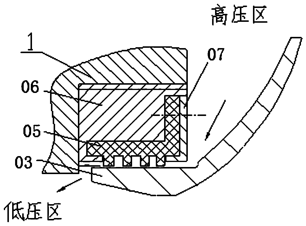
[0037] Such as Figure 4 to Figure 6 , a centrifugal wheel sealing structure suitable for low temperature environments, including a sealing ring; the sealing ring is sleeved outside the sealing flange 7 of the centrifugal wheel with a diameter of φ180mm, and the base 101 of the sealing shell 1 is fixed on the pump shell 6; wherein , the sealing ring includes a sealing shell 1, a metal annular plate 2 made of forged aluminum, a polytrifluoroethylene annular plate 3 and a pressure plate 4, and the sealing shell 1 is made of stainless steel with high rigidity; the sealing shell 1 includes a circular ring A shaped base 101 and a hollow cylindrical shell 102, the shell 102 is vertically fixed on the base 101. A plurality of polytrifluoroethylene annular plates 3 and a plurality of metal annular plates 2 are alternately placed in the housing 102, the number of polytrifluoroethylene annular plates 3 is 4, and the number of metal annular plates 2 is 3; the polytrifluoroethylene annula...

Embodiment 2

[0039] Such as Figure 4 to Figure 6 , a centrifugal wheel sealing structure suitable for low temperature environments, including a sealing ring; the sealing ring is sleeved outside the sealing flange 7 of the centrifugal wheel with a diameter of φ180mm, and the base 101 of the sealing shell 1 is fixed on the pump shell 6; wherein , the sealing ring includes a sealing shell 1, a metal annular plate 2 made of forged aluminum, a polytrifluoroethylene annular plate 3 and a pressure plate 4, and the sealing shell 1 is made of stainless steel with high rigidity; the sealing shell 1 includes a circular ring A shaped base 101 and a hollow cylindrical shell 102, the shell 102 is vertically fixed on the base 101. A plurality of polytrifluoroethylene annular plates 3 and a plurality of metal annular plates 2 are alternately placed in the housing 102, the number of polytrifluoroethylene annular plates 3 is 6, and the number of metal annular plates 2 is 5; the polytrifluoroethylene annula...

Embodiment 3

[0041] Such as Figure 4 to Figure 6, a centrifugal wheel sealing structure suitable for low temperature environments, including a sealing ring; the sealing ring is sleeved outside the sealing flange 7 of the centrifugal wheel, and the base 101 of the sealing casing 1 is fixed on the pump casing 6; wherein, the sealing ring includes The sealing case 1, the metal annular plate 2 made of forged aluminum, the polytrifluoroethylene annular plate 3 and the pressure plate 4, the sealing case 1 is made of stainless steel with high rigidity; the sealing case 1 includes a circular base 101 and a hollow cylindrical casing 102, the casing 102 is vertically fixed on the base 101. A plurality of polytrifluoroethylene annular plates 3 and a plurality of metal annular plates 2 are alternately placed in the housing 102, the number of polytrifluoroethylene annular plates 3 is 9, and the number of metal annular plates 2 is 8; the polytrifluoroethylene annular plates 3 is placed on the bottom o...


PUM


Abstract

The invention belongs to a sealing structure and a sealing structure of a centrifugal wheel. In order to solve the technical problem that in the prior art, the sealing effect is reduced as a metal seal ring is easy to rub with a sealing convex edge of the centrifugal wheel to explode in a low-temperature environment, a non-metal seal ring which is poor in integral rigidity is easy to degenerate and a non-metal inner core which is integrally processed and is easily deformed in a sandwiched seal ring is easy to lead to eccentric wear with the sealing convex edge of the centrifugal wheel, the invention provides a seal ring and the sealing structure of the centrifugal wheel suitable for the low-temperature environment. The seal ring comprises a sealing shell, a metal annular plate, a polytrifluoroethylene annular plate and a pressure plate. The polytrifluoroethylene annular plate and the metal annular plate are placed in a shell alternately, the polytrifluoroethylene annular plate is placed at the bottom of the sealing shell, and the polytrifluoroethylene annular plate and the metal annular plate form a labyrinth seal; and the pressure plate is aligned to the upper surface of the shellfor being riveted and fixed. According to the sealing structure of the centrifugal wheel suitable for the low-temperature environment, the seal ring is arranged outside the sealing convex edge of thecentrifugal wheel in a sleeving manner, and a base of the sealing shell is fixed to a pump shell.

Description

technical field [0001] The invention belongs to a sealing structure and a sealing structure of a centrifugal wheel, in particular to a sealing ring and a sealing structure of a centrifugal wheel suitable for a low-temperature environment. Background technique [0002] The sealing ring of a liquid rocket engine turbo pump plays an important role in improving the efficiency of the pump, especially the sealing ring used in cryogenic liquid oxygen propellants. The performance and reliability of the sealing ring are directly related to the performance and reliability of the turbo pump. Therefore, it is required to consider not only the safety of the material when it rubs against the metal centrifugal wheel under low temperature working conditions, but also the reliability and sealing performance of the sealing ring. [0003] The existing centrifugal wheel sealing structure is as follows: [0004] Such as figure 1 , the sealing ring is made of metal material, the overall process...

Claims


Application Information

Patent Timeline
Patent Type & Authority Applications(China)
IPC IPC(8): F04D29/08
CPCF04D29/086
Inventor 付瑜白东安叶树波徐楠王魁赵瑞勇刘军年
Owner XIAN AEROSPACE PROPULSION INST
Why Eureka
Eureka Blog
Learn More