
Camera with hand-shake correction function

A technology for a camera device and a camera lens, which is applied in the directions of printing devices, projection devices, installation, etc., can solve the problems such as the overall length and bending of the curved optical system, so as to reduce the performance impact, the high-efficiency anti-shake mechanism, Effect

Active Publication Date: 2021-12-14
AAC OPTICS (CHANGZHOU) CO LTD
View PDF8 Cites 0 Cited by
  • Summary
  • Abstract
  • Description
  • Claims
  • Application Information

AI Technical Summary

Problems solved by technology

However, for example, in a small optical device mounted on a portable electronic device, it is difficult to directly mount a zoom optical system with a long optical length on the portable electronic device, and it is necessary to adopt a structure such as a bend.
In addition, there is a tendency for the total optical length to be longer in an optical device equipped with a device called an optical zoom that includes a device that changes the optical magnification on the imaging surface by moving the optical system in the direction of the optical axis.
[0004] In the optical system using this curved structure, the case where the lenses arranged before and after the prism or mirror for bending light are used for shake correction, or the case where the lens group moves by optical zooming is used. In the case of a structure in which a part of the lens is movable by shake correction, however, in portable electronic devices that are miniaturized, by using a shake correction structure that uses lenses arranged in front and behind them, a shake correction structure that makes a part of the lenses of the lens group move , it is possible to make the overall length of the curved optical system longer, or it may become a structure in which a part of the shape must protrude

Method used


Image

  • Camera with hand-shake correction function
  • Camera with hand-shake correction function
  • Camera with hand-shake correction function

Examples


Embodiment Construction

[0048] Below, while referring to the attached Figure 1 The present invention will be described in detail.

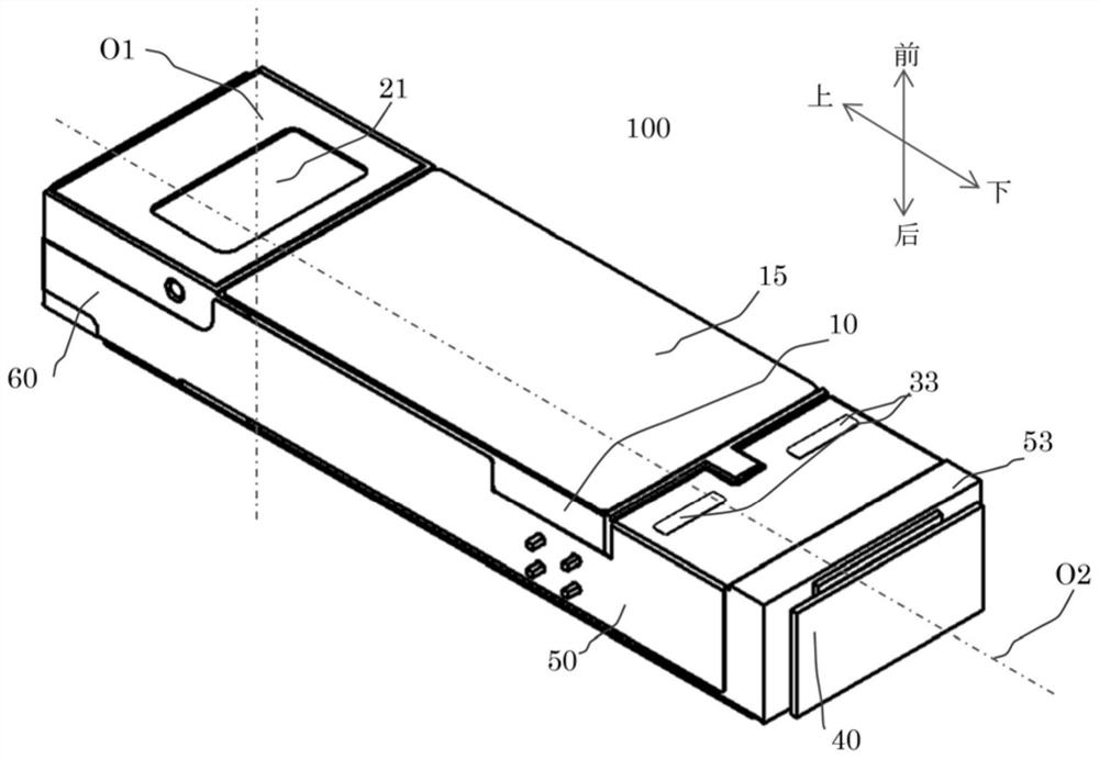
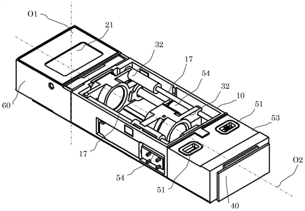
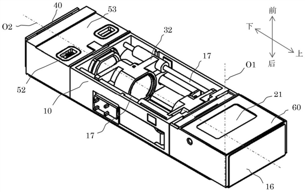
[0049] Figure 1 to Figure 7 It is a drawing showing the curved imaging device 100 of the present invention.

[0050] Figure 1 to Figure 16 The imaging device and its constituent elements according to the embodiment of the present invention are shown.

[0051] The imaging optical system of the curved imaging device 100 is a curved optical system composed of a prism 21 as a reflection member, an imaging lens group 31 , and an imaging element 41 from the object side, and light beams are reflected by the prism 21 .

[0052] The light beam from the subject that is incident on the incident surface 21-a of the prism 21 along the first optical axis O1 is reflected by the reflective surface 21-b of the prism 21 in a direction along the second optical axis O2 and is emitted from the outgoing surface 21-a. c shot out. Next, the light beam passes through the imaging lens gro...


PUM


Abstract

The present invention provides an imaging device having a curved optical system and an anti-shake mechanism without increasing the size of the device. The optical system has a reflection member that bends the optical axis, and includes a reflection member, an imaging lens group, and an imaging element in order from the object side, and the reflection member is aligned with the optical axis of the imaging lens group and an object reflected by the reflection member. The axis perpendicular to the plane formed by the optical axis on the object side and the axis parallel to the reflected optical axis on the object side are used as rotation axes to perform hand shake correction.

Description

technical field [0001] The invention relates to an image pickup device with a hand shake correction function. Background technique [0002] With the rapid development of photographic technology, lens driving devices are widely used in a large number of photographic devices. It is especially accepted by consumers to apply lens driving devices to various portable electronic devices, such as mobile phones and tablet computers. [0003] The driving mechanism of the lens driving device suitable for common portable electronic equipment is generally formed by a coil and a magnetic steel, and the coil is fixed on the outer periphery of the lens holder. When current is applied to the coil, the coil can move the lens holder along the optical axis direction of the lens through the action of electromagnetic force to align the focus. In addition, when the user takes an image while holding the electronic device with his hand, the camera shake of the lens driving device due to hand shake...

Claims


Application Information

Patent Timeline
Patent Type & Authority Patents(China)
IPC IPC(8): G03B5/00G03B30/00
CPCG03B5/00G02B27/646G02B7/1828G02B13/0065G03B17/17G03B30/00G03B2205/0023G03B2205/0069G02B7/182
Inventor 色摩和雄
Owner AAC OPTICS (CHANGZHOU) CO LTD
Learn More