Display panel and display device

A technology of display panel and display area, which is applied to instruments, semiconductor devices, computing, etc., can solve the problems of difficult electrical connection between touch traces and metal trace layers, and achieve the effect of omitting FPC and simplifying process steps.

Active Publication Date: 2020-05-12
KUNSHAN GO VISIONOX OPTO ELECTRONICS CO LTD
View PDF7 Cites 5 Cited by
  • Summary
  • Abstract
  • Description
  • Claims
  • Application Information

AI Technical Summary

Problems solved by technology

[0003] However, there is a height difference between the touch layer and the metal wiring layer where the touch wiring is located due to the stacking of multiple functional film layers and cover plates. The existence of this height difference makes the gap between the touch wiring and the metal wiring layer It is difficult to achieve electrical connection

Method used


Image

  • Display panel and display device
  • Display panel and display device
  • Display panel and display device

Examples


Embodiment Construction

[0022] The following will clearly and completely describe the technical solutions in the embodiments of the present application with reference to the drawings in the embodiments of the present application. Obviously, the described embodiments are only some of the embodiments of the present application, not all of them. Based on the embodiments in this application, all other embodiments obtained by persons of ordinary skill in the art without making creative efforts belong to the scope of protection of this application.

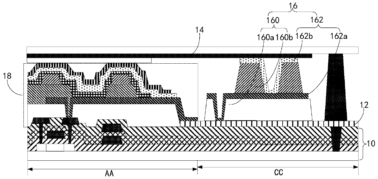
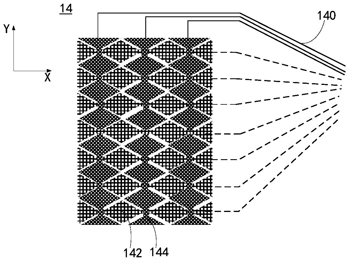
[0023] see figure 1 , figure 1 It is a schematic structural diagram of an embodiment of the display panel of the present application, figure 2 for figure 1 A schematic top view of an embodiment of the middle touch layer. The display panel defines a display area AA and a non-display area CC located around the display area AA. The non-display area CC can also be called a frame area. The display panel includes: an array layer 10 , a metal wiring layer 12 , a...


PUM


Abstract

The invention provides a display panel and a display device. The display panel defines a display area and a non-display area located around the display area, and the display panel comprises an array layer covering the display area and the non-display area; a metal wiring layer covering part of the array layer located in the non-display area, wherein one end of the metal wiring layer is electrically connected with a touch chip; a touch layer arranged on the side, away from the array layer, of the metal wiring layer and comprising a plurality of touch leads, wherein the touch leads extend to thenon-display area from the display area; functional film layers located between the array layer and the touch layer and located in the display area; a heightening conductive structure located betweenthe metal wiring layer and the touch layer, wherein the touch leads are electrically connected with the metal wiring layer through the heightening conductive structure and the heightening conductive structure and at least one functional film layer are arranged on the same layer. By means of above mode, the touch leads can be electrically connected with the metal wiring layer through the heightening conductive structure.

Description

technical field [0001] The present application relates to the field of display technology, in particular to a display panel and a display device. Background technique [0002] At present, a display panel packaged with a hard screen generally includes an array layer, a plurality of functional film layers, a cover plate, and a touch layer that are stacked in sequence; wherein, the touch wiring of the touch layer is arranged on the side of the cover plate facing away from the array layer. A metal wiring layer is arranged on the frame area of ​​the array layer, and one end of the touch wiring needs to be connected to the metal wiring layer in a certain way, and then connected to the touch chip through the metal wiring layer. [0003] However, there is a height difference between the touch layer and the metal wiring layer where the touch wiring is located due to the stacking of multiple functional film layers and cover plates. The existence of this height difference makes the gap...

Claims


Application Information

Patent Timeline
Patent Type & Authority Applications(China)
IPC IPC(8): G06F3/041
CPCG06F3/0412G06F2203/04103G06F3/0446G06F3/0443G06F2203/04112H01L27/124H01L27/1214G06F3/04164
Inventor 彭兆基
Owner KUNSHAN GO VISIONOX OPTO ELECTRONICS CO LTD
Why Eureka
Try Eureka