
Electrode step-by-step printing method of high-efficiency solar cell

A technology of solar cells and printing methods, applied to circuits, photovoltaic power generation, electrical components, etc., to achieve the effects of improving conversion efficiency, high fault tolerance, and good lap reliability

Inactive Publication Date: 2020-05-12
GUANGDONG AIKO SOLAR ENERGY TECH CO LTD
View PDF6 Cites 5 Cited by
  • Summary
  • Abstract
  • Description
  • Claims
  • Application Information

AI Technical Summary

Problems solved by technology

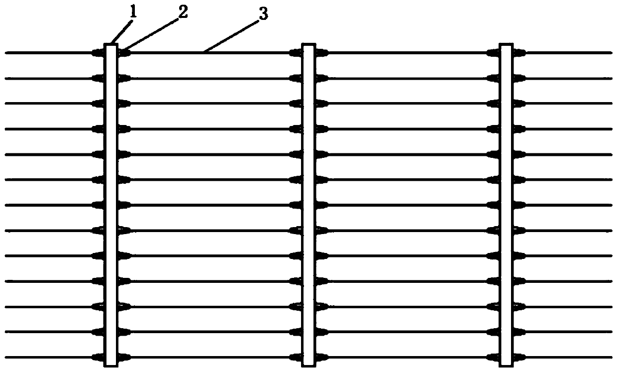
[0007] The technical problem to be solved by the present invention is to provide a step-by-step printing method for electrodes of high-efficiency solar cells, which can effectively avoid the poor appearance and EL problems caused by the alignment offset of the existing step-by-step printing and the bad printing problems of parallel overprinting at overlapping joints At the same time, it avoids the welding problem of the component end caused by the poor lap of the main grid and the fine grid of the battery

Method used


Image

  • Electrode step-by-step printing method of high-efficiency solar cell
  • Electrode step-by-step printing method of high-efficiency solar cell
  • Electrode step-by-step printing method of high-efficiency solar cell

Examples


Embodiment 1

[0081] Use 156.75*156.75mm size battery;

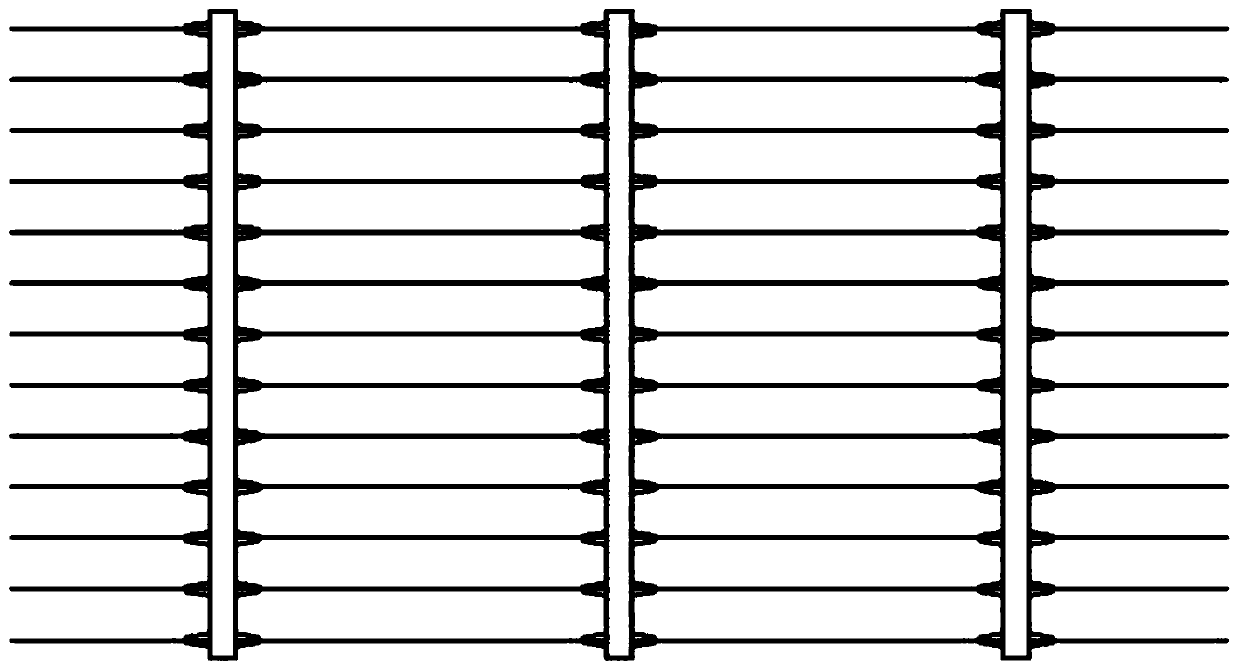
[0082] On the front of the battery, the busbar 1 is first printed according to the busbar pattern. The busbar 1 includes the busbar 11 in the welding area and the busbar lap structure 12. The width of the busbar 11 in the welding area is 700 μm, and the busbar lap structure 12 It is an isosceles triangle, the side length of the triangle is 713.5μm, and the apex angle is 60°. The paste for printing the busbar is non-burn-through silver paste, and the screen is a 325-mesh screen printing screen;

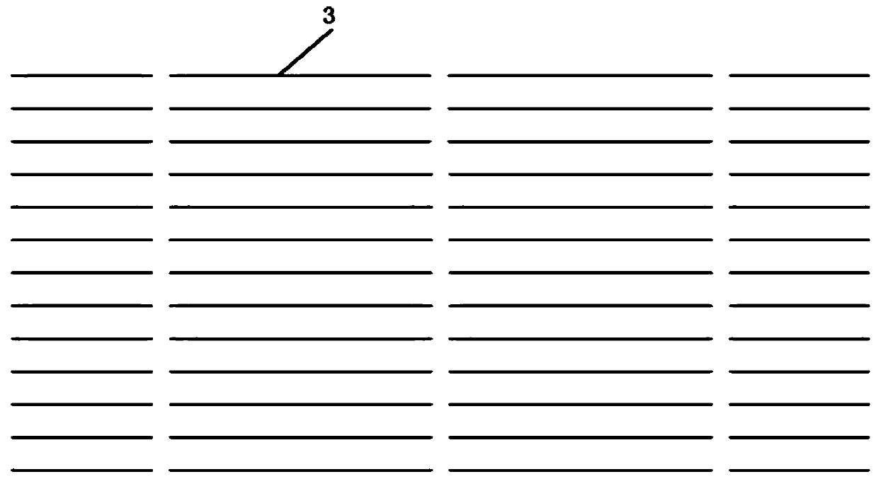
[0083] Then, the fine grid 3 is printed according to the fine grid pattern. The fine grid 3 includes a thin grid line 31 and a thin grid overlapping structure 32 connecting two adjacent thin grid lines 31. The width of the thin grid line 31 is 30 μm. The overlapping structure 32 is V-shaped, the line width of the fine grid overlapping structure is 100 μm, and the paste for printing the fine grid is a burn-through silver paste;

[0084] The co...

Embodiment 2

[0086] Use 158.75*158.75mm size battery;

[0087] On the front of the battery, the busbar 1 is first printed according to the busbar pattern. The busbar 1 includes the busbar 11 in the welding area and the busbar lap structure 12. The width of the busbar 11 in the welding area is 700 μm, and the busbar lap structure 12 It is an isosceles triangle, the side length of the triangle is 722.7μm, and the apex angle is 60°. The paste for printing the busbar is non-burn-through silver paste, and the screen is a 325-mesh screen printing screen;

[0088] Then, the fine grid 3 is printed according to the fine grid pattern. The fine grid 3 includes a thin grid line 31 and a thin grid overlapping structure 32 connecting two adjacent thin grid lines 31. The width of the thin grid line 31 is 30 μm. The overlap structure 32 is groove-shaped, the length of the top edge is 481.8 μm, the angle between the top edge and the waist edge is 120°, and the line width of the fine grid overlap structure ...

Embodiment 3

[0091] Use 161.7*161.7mm size battery;

[0092] On the front side of the battery, firstly, the thin grid 3 is printed according to the thin grid pattern. The thin grid 3 includes thin grid lines 31 and a thin grid overlapping structure 32 connecting two adjacent thin grid lines 31. The width of the thin grid lines 31 is 30 μm, the fine grid overlapping structure 32 is V-shaped, the line width of the fine grid overlapping structure is 100 μm, and the paste for printing the fine grid is a burn-through silver paste;

[0093] Then, the busbar 1 is printed according to the busbar pattern. The busbar 1 includes a busbar line 11 in the welding area and a busbar lap structure 12. The width of the busbar line 11 in the welding area is 700 μm, and the busbar lap structure 12 is an isosceles trapezoid. , the length of the base of the isosceles trapezoid is 736.2μm, the angle between the base and the waist is 60°, the paste for printing the busbar is non-burn-through silver paste, and the...


PUM


Abstract

The invention discloses an electrode step-by-step printing method for a high-efficiency solar cell, and the method comprises the steps: firstly printing a main grid according to a main grid pattern, enabling the main grid to comprise a welding region main grid line and a main grid lap joint structure, and enabling the main grid lap joint structure to be connected with the welding region main gridline; then printing a fine grid according to the fine grid pattern, wherein the fine grid comprises fine grid lines and a fine grid lap joint structure for connecting two adjacent fine grid lines, thedistance between every two adjacent main grids is the distance between the main grid lap joint structures, the distance between the main grid lap joint structures is matched with the length of the thin grid lines, and the main grid lap joint structures and the thin grid lap joint structures are intersected and overprinted, so that at least two intersected and overprinted intersection points are formed on the two sides of each main grid and the two sides of each thin grid line respectively. By adopting the method, the problems of poor appearance and EL caused by step-by-step printing alignmentoffset and poor printing caused by parallel overprinting at the lap joint position are effectively avoided, and meanwhile, the problem of assembly end welding caused by poor lap joint of the main grid and the fine grid of the battery is avoided.

Description

technical field [0001] The invention relates to the manufacturing field of solar cells, in particular to a step-by-step electrode printing method for high-efficiency solar cells. Background technique [0002] In recent years, the mainstream products of solar cells have transitioned from traditional cells to high-efficiency PERC cells. As the conversion efficiency of cell products tends to be a bottleneck and the production process continues to mature, solar cells face huge challenges in continuing to reduce costs and increase efficiency. [0003] At present, among the non-silicon production costs of solar cells, the cost of silver paste ranks first. There are three main methods of printing electrodes at present: (1) a single screen printing technique; (2) a secondary printing technique: printing the fine grid first, and then printing the main fine grid together again. (3) Step-by-step printing technology: The busbar and the fine grid are printed separately. [0004] like ...

Claims


Application Information

Patent Timeline
Patent Type & Authority Applications(China)
IPC IPC(8): H01L31/0224H01L31/05H01L31/18
CPCH01L31/022433H01L31/0508H01L31/188Y02E10/50Y02P70/50
Inventor 杨苏平黄石明尧海华吴波林纲正陈刚
Owner GUANGDONG AIKO SOLAR ENERGY TECH CO LTD
Learn More