Supercharge Your Innovation With Domain-Expert AI Agents!

Camera module

A camera module and area technology, which is applied in the directions of cameras, camera bodies, printed circuits connected with non-printed electrical components, etc., can solve the problems of increasing the size and volume of the camera module, increasing the manufacturing process and manufacturing cost of the camera module, etc. , to achieve the effect of reducing the overall process and reducing the manufacturing cost

Active Publication Date: 2020-05-12
LG INNOTEK CO LTD
View PDF4 Cites 0 Cited by
  • Summary
  • Abstract
  • Description
  • Claims
  • Application Information

AI Technical Summary

Problems solved by technology

[0005] However, this leads to other disadvantages as described below: Since a separate PCB (Printed Circuit Board) is mounted on the RGB module to allow it to be placed near the ToF sensor, it increases the manufacturing process and cost of the camera module, and also Increased camera module size and bulk

Method used


Image

  • Camera module
  • Camera module
  • Camera module

Examples


Embodiment Construction

[0028] Some exemplary embodiments of the present invention will be described in detail with reference to the accompanying drawings. All exemplary embodiments explained below should be understood as merely exemplary to help understanding of the present invention, and these embodiments can be embodied in many different forms, and should not be construed as being limited to the embodiments set forth herein. In addition, although obstacles are encountered in understanding the exemplary embodiments of the present invention, in explaining the exemplary embodiments of the present invention, a detailed explanation of some related well-known functions or known elements will be omitted.

[0029] To aid understanding of the present invention, the drawings are not drawn to scale and may not accurately reflect precise structural dimensions or may be exaggerated. In describing the reference numeral of each element, the same element will be assigned the same reference numeral if possible des...


PUM


Abstract

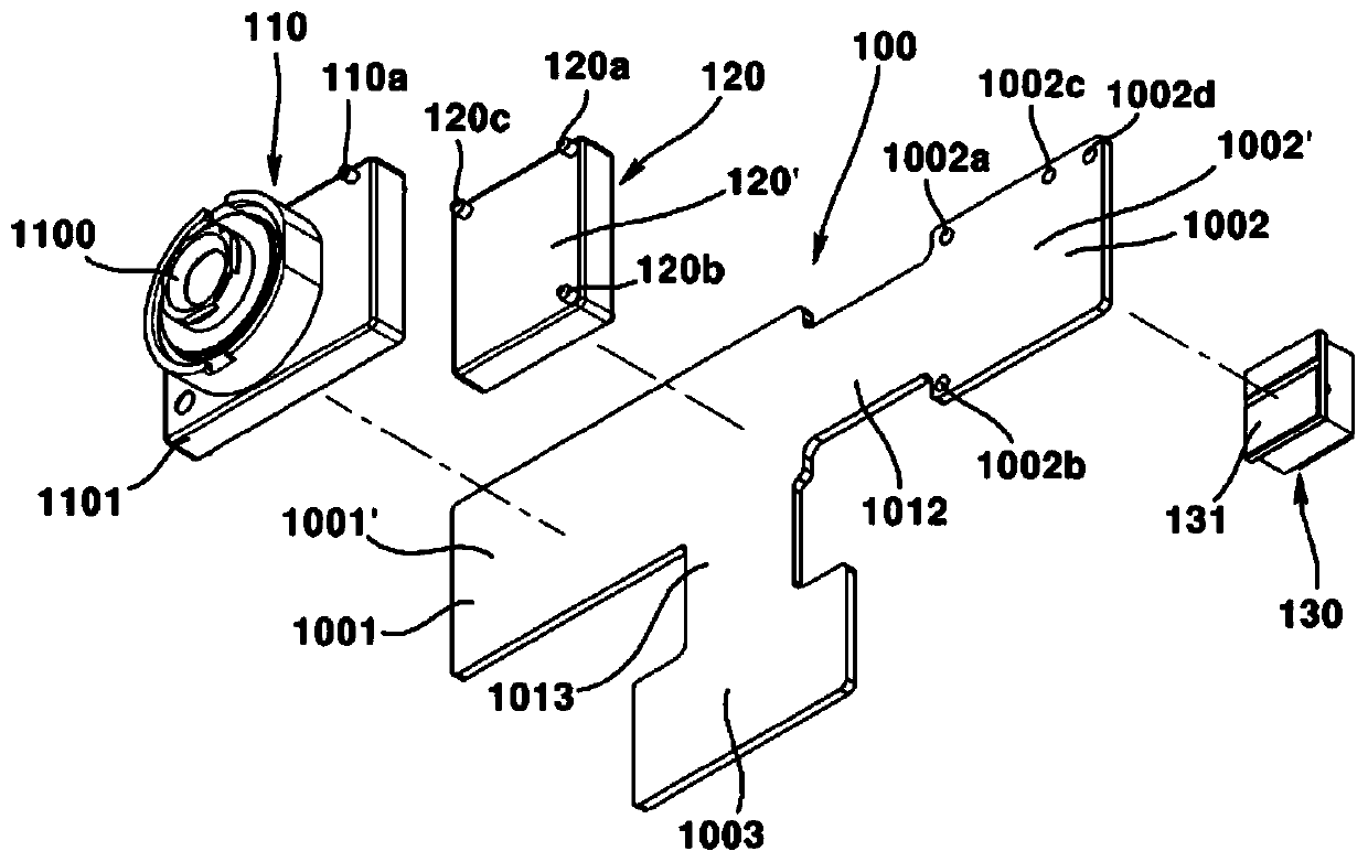
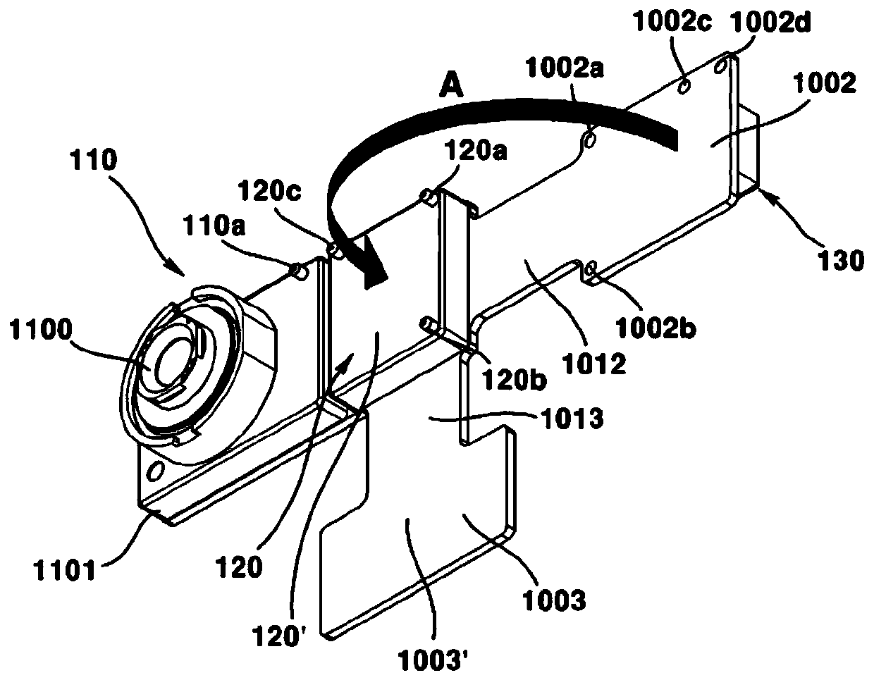
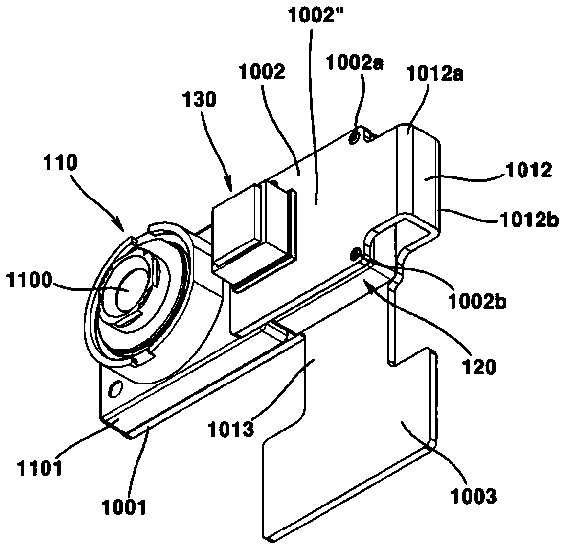
The present embodiment relates to a camera module comprising: a substrate having a first region, a second region, and a first connection portion between the first region and the second region; a lensunit disposed in the first region of the substrate and including a lens holder in which a lens and a lens barrel are disposed; a heat sink part disposed adjacent to the lens unit in the first region of the substrate; and a light source element disposed above the heat sink part and disposed in the second region of the substrate, wherein the lens unit is disposed on a first surface of the substrate,the light source element is disposed on a second surface of the substrate, the first connection portion is bent at the side surface of the heat sink part so as to connect the first region and the second region, the first connection portion includes a flexible substrate, and the flexible substrate is disposed between the first surface and the second surface of the substrate.

Description

technical field [0001] The present embodiment relates to a camera module, and more particularly, to a camera module including an image acquisition sensor and a light source. Background technique [0002] The current trend is that research on 3D cameras capable of acquiring distance information about objects, and particularly devices capable of acquiring 3D depth images for face recognition, is currently increasing. [0003] Along with the above-mentioned trend, a ToF (Time of Flight) module has been introduced as a depth image acquisition device. The ToF module acquires a depth image by measuring the time of flight of light from when the light is reflected from the object to when the light is received by the light receiving part after the illumination light is irradiated on the object. [0004] However, the method has the disadvantage that noise and distortion are generated when the distance from the object is large, thereby suddenly reducing the accuracy of the information...

Claims


Application Information

Patent Timeline
Patent Type & Authority Applications(China)
IPC IPC(8): G03B17/12G03B17/55H04N5/225H05K1/18
CPCH05K1/18G03B17/55G03B2205/0046H04N23/56H04N23/57H04N23/55G03B17/12G02B7/028G03B2217/002H04N13/271H04N13/254H04N23/54G03B30/00
Inventor 金玟
Owner LG INNOTEK CO LTD
Features
  • R&D
  • Intellectual Property
  • Life Sciences
  • Materials
  • Tech Scout
  • Unparalleled Data Quality
  • Higher Quality Content
  • 60% Fewer Hallucinations
Learn More