Supercharge Your Innovation With Domain-Expert AI Agents!

Roller kiln sintering temperature control method and system

A technology of sintering temperature and control method, applied in the furnace control device, furnace, furnace type and other directions, can solve the problems of burning out heating components, power grid impact, etc., and achieve the effect of prolonging the service life

Active Publication Date: 2021-11-12
HUNAN JINLU TECH CO LTD
View PDF3 Cites 2 Cited by
  • Summary
  • Abstract
  • Description
  • Claims
  • Application Information

AI Technical Summary

Problems solved by technology

[0004] The invention provides a roller kiln sintering temperature control method and its system, which are used to solve the problem of burning out heating due to the large current generated by controlling the heating components in a short time during the adjustment process of the existing road kiln sintering temperature control method. The technical problem of the impact of components on the power grid at the same time

Method used


Image

  • Roller kiln sintering temperature control method and system
  • Roller kiln sintering temperature control method and system
  • Roller kiln sintering temperature control method and system

Examples


Embodiment 1

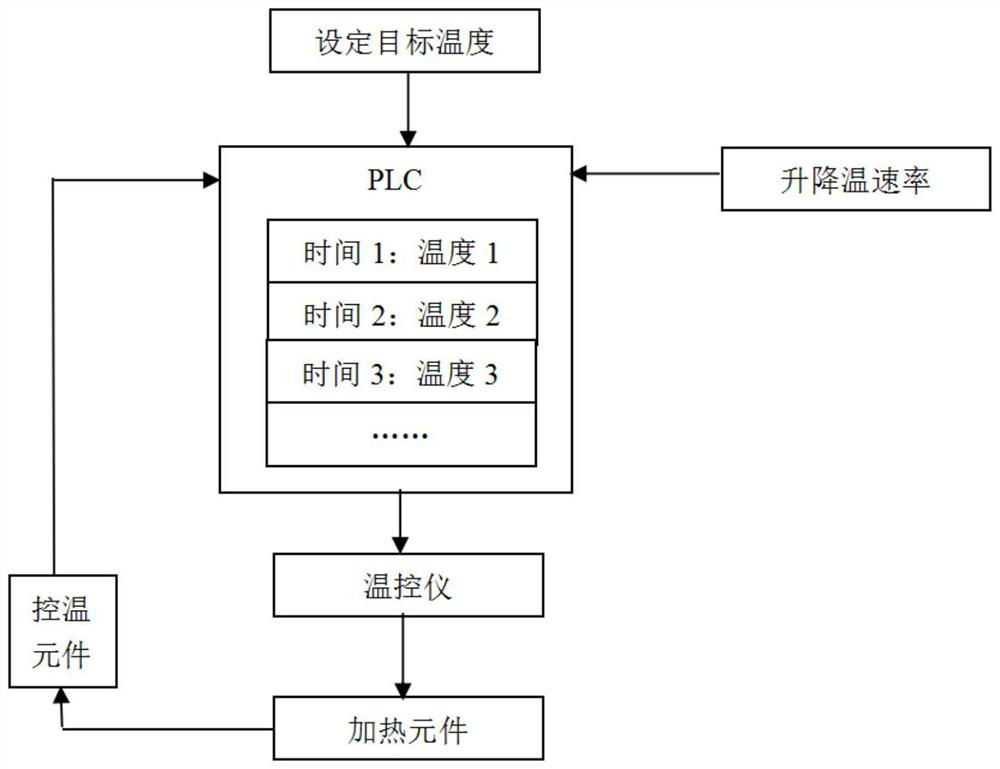
[0023] like figure 1 As shown, this implementation discloses a method for controlling the sintering temperature of a roller kiln, which includes the following steps:

[0024] Determine the scientific heating and / or cooling target temperature zone, the optimal heating rate and / or the optimal cooling rate of the roller kiln according to the material of the refractory lining of the roller kiln;

[0025] Calculate the target of each preset time node when the roller kiln is heated and / or cooled at the optimal heating rate and / or the optimal cooling rate in the target temperature zone of the roller kiln for heating and / or cooling temperature;

[0026] The heating power of the heating element of the roller kiln at each preset time node is controlled according to the target temperature at each preset time node, so that the heating element executes the target temperature at each preset time node.

[0027] In addition, in this embodiment, a computer system includes a memory, a process...

Embodiment 2

[0030] The second embodiment is an expanded embodiment of the first embodiment. The difference from the first embodiment is that the specific steps of the roller kiln sintering temperature control method are refined, and the structure and the structure of the roller kiln sintering temperature control system are detailed. The functionality has been expanded to include the following:

[0031] In this embodiment, according to the material of the lining of the roller kiln, the influence of heating and cooling on the service life of the lining is fully considered, especially the rapid heating and cooling is not conducive to the long-term use of the lining. Based on this, the target temperature zone is determined to achieve a more scientific heating / cooling down, including the optimal heating rate and / or the optimal cooling rate) specifically includes: according to the set optimal heating / cooling rate, in multiple consecutive fixed time periods (for example, 5s-adjustment) multiple ...


PUM


Abstract

The invention discloses a roller kiln sintering temperature control method and a system thereof. According to the material of the lining refractory material of the roller kiln, the target temperature zone, the optimal heating rate and / or the scientific heating and / or cooling of the roller kiln are determined. optimal cooling rate; and calculate the roller kiln in the roller kiln heating and / or cooling target temperature zone with the optimal heating rate and / or optimal cooling rate when heating and / or cooling each The target temperature of the preset time node; and then control the heating power of the heating element of the roller kiln at each preset time node according to the target temperature of each preset time node, so that the heating element performs the described Compared with the existing technology, the target temperature can ensure that the temperature rises steadily without generating a large current that impacts the power grid, which is beneficial to protect the heating components and prolong the service life of the heating components.

Description

technical field [0001] The invention relates to the technical field of industrial kilns, in particular to a method and a system for controlling the sintering temperature of roller kilns. Background technique [0002] In the sintering process of roller kiln, different products have different process requirements. In the process of continuous feeding, the temperature in the furnace is changed to adapt to different products. The traditional temperature adjustment method is that workers are on the control cabinet. Manual adjustment of the temperature control module. When heating and cooling the furnace, the operator usually has to manually change the module parameters and record the data of each phase at regular intervals to ensure that the temperature curve meets the process requirements. The delay and error caused by this manual adjustment method will have a certain impact on the product quality. At the same time, the manually modified value is usually far away from the curre...

Claims


Application Information

Patent Timeline
Patent Type & Authority Patents(China)
IPC IPC(8): F27B9/40F27D19/00
CPCF27B9/40F27D19/00F27D2019/0025
Inventor 欧阳建高平立易焕能欧旭明廖栩枫
Owner HUNAN JINLU TECH CO LTD
Features
  • R&D
  • Intellectual Property
  • Life Sciences
  • Materials
  • Tech Scout
  • Unparalleled Data Quality
  • Higher Quality Content
  • 60% Fewer Hallucinations
Learn More