Overturning clamp for packaging chip

A technology for flipping jigs and chips, which is applied in the manufacture of electrical components, circuits, semiconductors/solid-state devices, etc., and can solve problems such as low effect, easily damaged leads, and heavy workload of personnel

Active Publication Date: 2020-05-15
CHONGQING DABIAO ELECTRONICS SCI & TECH
View PDF8 Cites 1 Cited by
  • Summary
  • Abstract
  • Description
  • Claims
  • Application Information

AI Technical Summary

Problems solved by technology

[0002] At present, the chip packaging process includes chip bonding, silver paste curing, lead welding, light inspection, injection molding, laser typing, high temperature curing, despilling, electroplating annealing, rib cutting and molding, etc.; Injection plastic between the leads around the chip; the existing excess flash is removed by cutting, but cutting is easy to damage the leads, so it is proposed to use weak acid to immerse the lead part, soak the flash together, and then rinse with high-pressure water to remove the overflow The existing overflow soaking method uses manual immersion, and then manually picks up the parts, the effect is low, and the workload of the personnel is large, so it is necessary to use a production line soaking structure to improve production efficiency; in the production line soaking process, because the current Some packaged chips have two rows of leads. The leads are located on both sides of the packaged chip. Soaking can only immerse the leads on the lower side of the packaged chip. Therefore, it is necessary to design a structure that can realize the flipping of the packaged chip, so that the leads on the upper side of the packaged chip can also be realized. immersion

Method used


Image

  • Overturning clamp for packaging chip
  • Overturning clamp for packaging chip
  • Overturning clamp for packaging chip

Examples


Embodiment

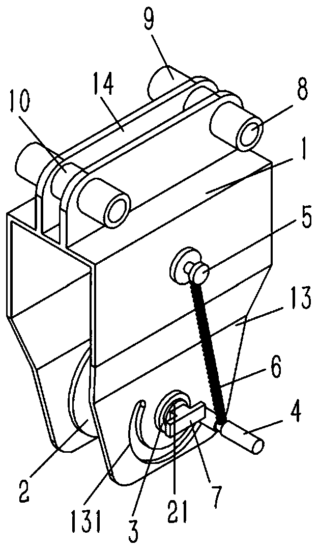
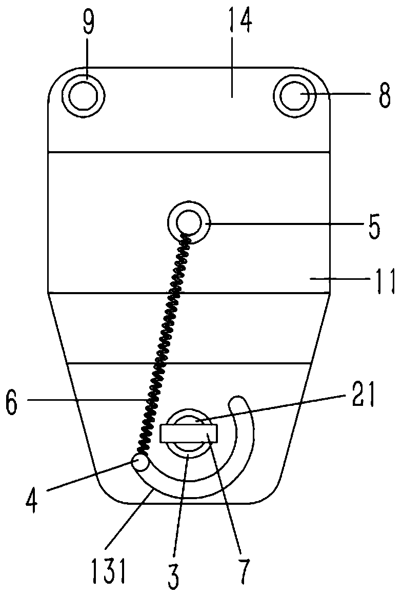
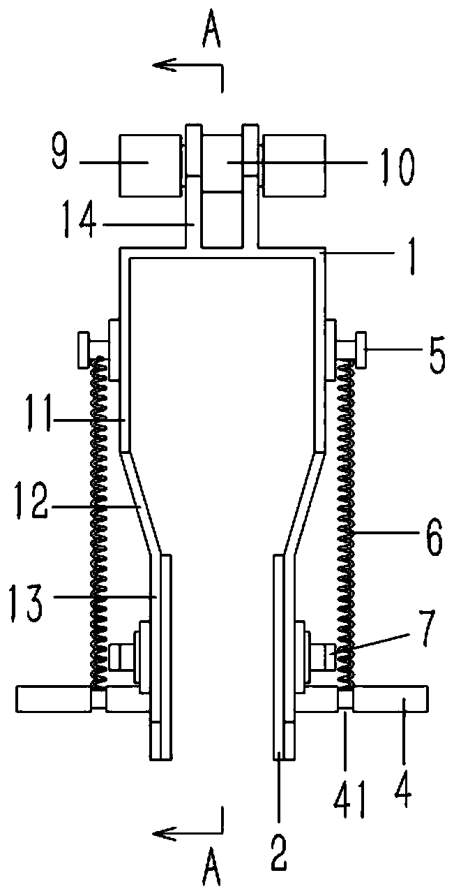
[0019] Example: see Figures 1 to 4 As shown, a flipping jig for packaged chips includes a horizontal top plate 1, the two sides of the top plate 1 are bent and formed with vertical side plates 11, and the lower side of the side plate 11 is bent and formed with an inwardly inclined oblique elastic Plate 12, the lower side of the inclined elastic plate 12 is bent to form a vertical splint 13, the inner wall of the splint 13 is against a circular support plate 2, and the middle part of the outer wall of the support plate 2 is formed with a fulcrum 21, The supporting shaft 21 passes through the splint 13 and fixes the limit sleeve 3. The splint 13 on the lower side of the supporting shaft 21 is formed with an arc-shaped guide groove 131, and a cylindrical driving rod 4 is inserted in the guiding groove 131. The inner end of the driving rod 4 is fixed on the support plate 2; the spring 6 is fixedly connected to the driving rod 4, the other end of the spring 6 is fixed on the fixed...


PUM


Abstract

The invention discloses an overturning clamp of a packaged chip. The overturning clamp comprises a horizontal top plate, and the two sides of the top plate are bent to form vertical side plates. The lower side edges of the side plates are bent to form inwards inclined elastic plates; the lower side edge of the inclined elastic plate is bent to form a vertical clamping plate; a circular supportingplate abuts against the inner side wall of the clamping plate, a supporting shaft is formed in the middle of the outer side wall of the supporting plate, the supporting shaft penetrates through the clamping plate to be inserted and sleeved with a fixed limiting sleeve, an arc-shaped guide groove is formed in the clamping plate on the lower side of the supporting shaft, a cylindrical shifting rod is inserted into the guide groove, and the inner end of the shifting rod is fixed to the supporting plate; a spring is fixedly connected to the shifting rod, the other end of the spring is fixed to a fixing block, and the fixing block is fixed to the outer wall of the side plate over the supporting shaft.

Description

technical field [0001] The invention relates to the technical field of chip packaging equipment, in particular to a flipping jig for packaging chips. Background technique [0002] At present, the chip packaging process includes chip bonding, silver paste curing, lead welding, light inspection, injection molding, laser typing, high temperature curing, despilling, electroplating annealing, rib cutting and molding, etc.; Injection plastic between the leads around the chip; the existing excess flash is removed by cutting, but cutting is easy to damage the leads, so it is proposed to use weak acid to immerse the lead part, soak the flash together, and then rinse with high-pressure water to remove the overflow The existing overflow soaking method uses manual immersion, and then manually picks up the parts, the effect is low, and the workload of the personnel is large, so it is necessary to use a production line soaking structure to improve production efficiency; in the production ...

Claims


Application Information

Patent Timeline
Patent Type & Authority Applications(China)
IPC IPC(8): H01L21/67H01L21/687
CPCH01L21/67121H01L21/67126H01L21/68707
Inventor 徐俊
Owner CHONGQING DABIAO ELECTRONICS SCI & TECH
Why Eureka
Try Eureka