Host with heat dissipation function for system integration
A system integration and host technology, applied in cooling/ventilation/heating transformation, cabinet/cabinet/drawer components, electrical components, etc., can solve the lack of fixed structure of the host, reduce the service life of the host, and the heat dissipation effect is general, etc. problems, to improve the effect of air circulation, increase the air supply area, and fix the effect better
- Summary
- Abstract
- Description
- Claims
- Application Information
AI Technical Summary
Problems solved by technology
Method used
Image
Examples
Embodiment 1
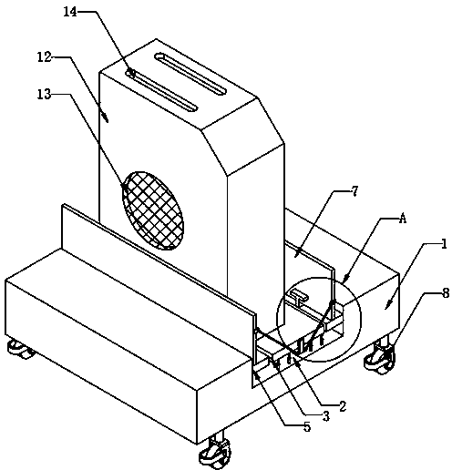
[0023] Such as Figure 1-Figure 4 As shown, a host for system integration with heat dissipation function includes a fixed base 1, a U-shaped groove 2 is opened in the middle of the fixed base 1, a fixed structure is arranged on the side wall of the U-shaped groove 2, and the bottom of the U-shaped groove 2 The ends are fixedly provided with a plurality of spring rods 4, and the tops of the plurality of spring rods 4 are all fixedly connected with the bottom end of the base plate 3, and the top of the base plate 3 is movably connected with a box body 12, and the middle part of both sides of the box body 12 is equipped with a Air outlet 13, the inside of two air inlets 13 is all laid with filter screen, the filter screen provided with can stop impurity from entering the inside of casing 12, helps to improve the service life of parts inside casing 12, the top of casing 12 There are two air outlets 14, and the insides of the two air outlets 14 are fitted with dust-proof nets. The ...
Embodiment 2
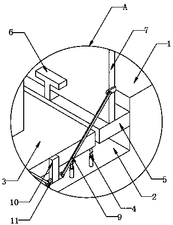
[0025] On the basis of Embodiment 1, such as figure 1 with figure 2 As shown, the fixed structure includes two side plates 5 that are respectively fixedly arranged on the side walls of the U-shaped groove 2, and the tops of the two side plates 5 are fixedly provided with a plurality of T-shaped blocks 6, and the plurality of T-shaped blocks 6 are all connected with each other. The top of clamping plate 7 is slidingly connected, and the middle part of bottom plate 3 two ends is all fixedly provided with fixed block 10, and the bottom of two fixed block 10 both sides and the middle part of two side clamping plates 7 both ends are all fixedly provided with shaft seat 11, two corresponding shafts Connecting rods 9 are hinged between the seats 11. After the box body 12 is placed on the top of the bottom plate 3, the bottom plate 3 moves downward under the action of gravity, and the connecting rods 9 drive the two splints 7 to the direction close to the box body 12. Movement, and ...
Embodiment 3
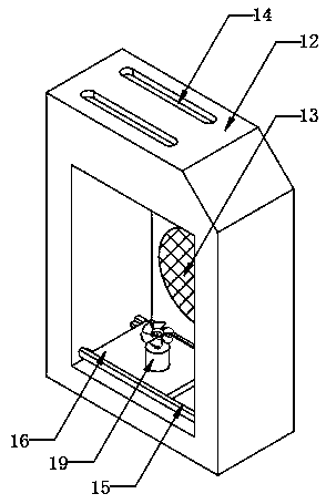
[0027] On the basis of embodiment one and embodiment two, such as image 3 with Figure 4 As shown, the heat dissipation structure includes two guide rails 15 fixedly arranged on the top of the side wall of the box body 12. The two guide rails 15 are respectively slidably connected to the two ends of the slide plate 16. The middle part of the top of the slide plate 16 is fixedly equipped with a cooling fan 19. The slide plate 16 A groove 17 is provided at the bottom of the groove, and a cam 18 is connected to the inside of the groove 17. One side of the cam 18 is fixedly connected with the output shaft of the drive motor 20. The drive motor 20 drives the cam 18 to rotate, and the cam 18 is inside the groove 17. In the process of turning, the slide plate 16 will be driven to reciprocate on the guide rail 15, which increases the air supply area of the cooling fan 19, and can blow air to different positions inside the box body 12, which is conducive to improving the heat dissip...
PUM
 Abstract
Description
Claims
Application Information
 - R&D
- Intellectual Property
- Life Sciences
- Materials
- Tech Scout
- Unparalleled Data Quality
- Higher Quality Content
- 60% Fewer Hallucinations
Browse by: Latest US Patents, China's latest patents, Technical Efficacy Thesaurus, Application Domain, Technology Topic, Popular Technical Reports.
© 2025 PatSnap. All rights reserved.Legal|Privacy policy|Modern Slavery Act Transparency Statement|Sitemap|About US| Contact US: help@patsnap.com


