An ankle comprehensive rehabilitation training device
A technology for rehabilitation training and ankle joints, applied in passive exercise equipment, physical therapy, etc., can solve the problems of affecting recovery effects, high work intensity of physical therapists, complex ankle joint structure, etc. The effect of machine cooperation is better, and the effect of man-machine cooperation is good
- Summary
- Abstract
- Description
- Claims
- Application Information
AI Technical Summary
Problems solved by technology
Method used
Image
Examples
Embodiment 1
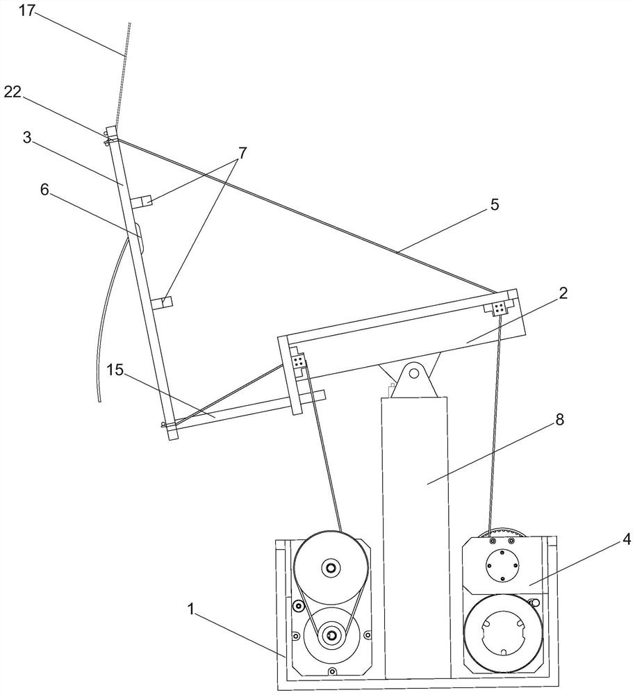
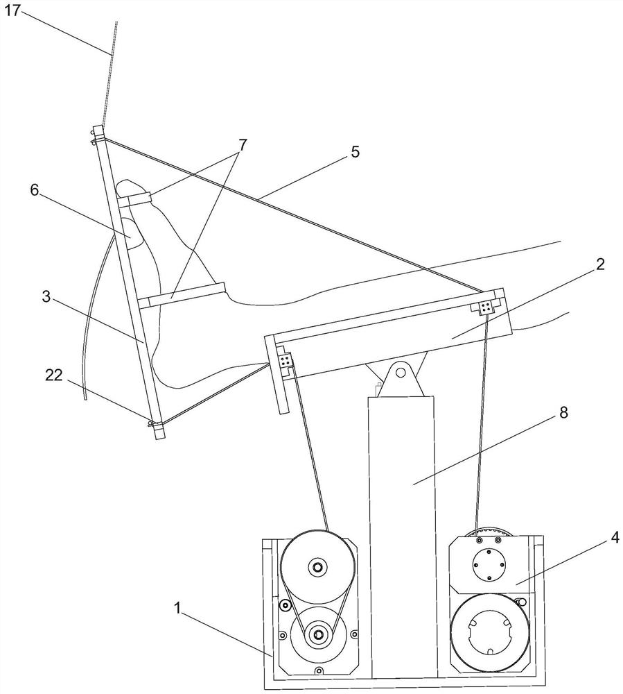
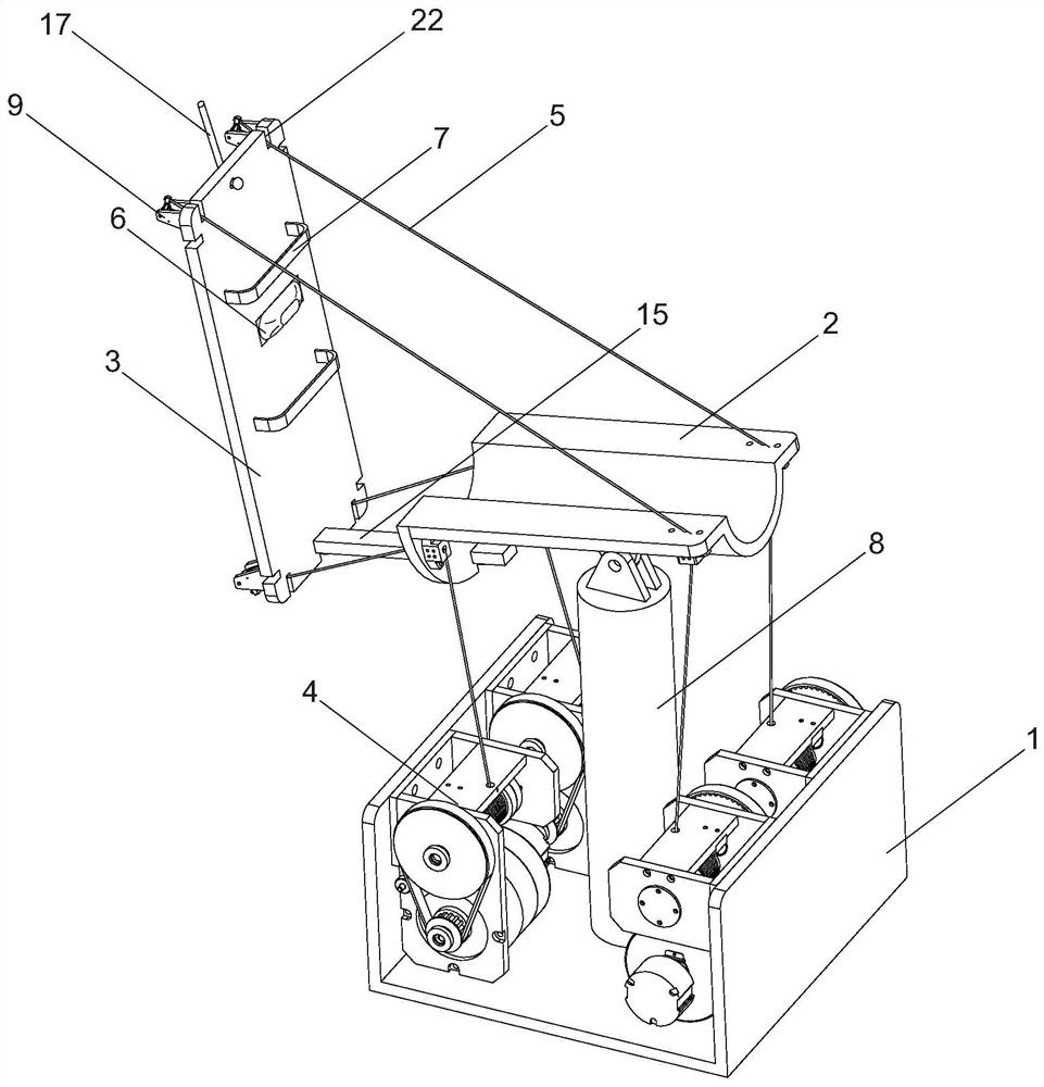
[0032] Such as figure 1 , figure 2 , Figure 6 As shown, a comprehensive ankle rehabilitation training device includes a base 1, a leg support frame 2, a sole support plate 3 and a rope drive module 4, the leg support frame 2 is hinged on the base 1, and the sole support plate 3 is connected to the leg The support frame 2 is detachably connected. The rope driving module 4 is fixed on the base 1, and the rope driving module 4 is connected with a drag cable 5 which can respectively apply tension to the upper, lower and left and right sides of the sole support plate 3, and the drag cable 5 passes through the leg support frame 2 and the sole support. Board 3 is connected. The sole support plate 3 is provided with a toe curl adjustment mechanism. The toe curl adjustment mechanism includes an airbag 6 and two parallel straps 7. The airbag 6 is embedded in the middle and upper part of the sole support plate 3, roughly corresponding to the connection between the sole of the foot and...
Embodiment 2
[0035] Such as Figure 3 to Figure 5 As shown, the sole support plate 3 is also provided with a cable steering adjustment mechanism, the cable steering adjustment mechanism includes a rotating base 23 and a pressure ring 16, the back of the sole support plate 3 is provided with four base installation blind holes, and the rotation base Seat 23 is circular and is adapted to be installed in the blind hole of the base, so that the rotating base 23 is rotatably connected to the sole support plate 3, and the fixed part of the cable end point is arranged on the rotating base 23 instead of as implemented. In example 1, it is a ring structure directly fixed on the sole support plate 3 . The pressure ring 16 is pressed on the junction of the base installation blind hole and the rotation base 23, and is fixed on the sole support plate 3 by screws, so that the rotation base 23 will not be dislocated from the base installation blind hole. The rotating base 23 is provided with a variable s...
Embodiment 3
[0038] There are six rope drive modules 4, which control six stay cables 5, and the six stay cables 5 correspond to the four corners connected to the sole support plate 3 and the middle parts on both sides respectively. All the other are with embodiment 1.
PUM
 Abstract
Description
Claims
Application Information
 - R&D
- Intellectual Property
- Life Sciences
- Materials
- Tech Scout
- Unparalleled Data Quality
- Higher Quality Content
- 60% Fewer Hallucinations
Browse by: Latest US Patents, China's latest patents, Technical Efficacy Thesaurus, Application Domain, Technology Topic, Popular Technical Reports.
© 2025 PatSnap. All rights reserved.Legal|Privacy policy|Modern Slavery Act Transparency Statement|Sitemap|About US| Contact US: help@patsnap.com


