Upper limb rehabilitation training equipment

A technology for rehabilitation training and equipment, applied in gymnastics equipment, sports accessories, etc., can solve the problems of patients' upper limb fatigue, poor training effect, and reduce the scope of application of upper limb rehabilitation training equipment, so as to improve the effect of rehabilitation training, increase the scope of application, and avoid Effects of upper body fatigue

Inactive Publication Date: 2022-06-03
常州江苏大学工程技术研究院
View PDF0 Cites 0 Cited by
  • Summary
  • Abstract
  • Description
  • Claims
  • Application Information

AI Technical Summary

Problems solved by technology

[0005] The object of the present invention is to provide a kind of upper limb rehabilitation training equipment, through limit chute, threaded column, sleeve pipe, first support plate, second support plate, spring, internal thread push ring, first annular groove and training mechanism The design solves the problem that the existing upper limb rehabilitation training devices generally cannot perform front and rear training and left and right training at the same time, and the rehabilitation trainers cannot receive comprehensive rehabilitation training, and the training effect is poor, which is not conducive to the rapid recovery of the rehabilitation trainers. Realize the effective support of the upper limbs, long-term training will lead to fatigue of the upper limbs of the patient, which is not conducive to the rehabilitation training of the upper limbs of the patient, and the height of the upper limb rehabilitation training device cannot be flexibly adjusted according to the height of the patient's upper limbs, which greatly reduces the scope of application of the upper limb rehabilitation training device question

Method used


Image

  • Upper limb rehabilitation training equipment
  • Upper limb rehabilitation training equipment
  • Upper limb rehabilitation training equipment

Examples


Embodiment Construction

[0016] The technical solutions in the embodiments of the present invention will be clearly and completely described below with reference to the accompanying drawings in the embodiments of the present invention. Obviously, the described embodiments are only a part of the embodiments of the present invention, but not all of the embodiments. Based on the embodiments of the present invention, all other embodiments obtained by those of ordinary skill in the art without creative efforts shall fall within the protection scope of the present invention.

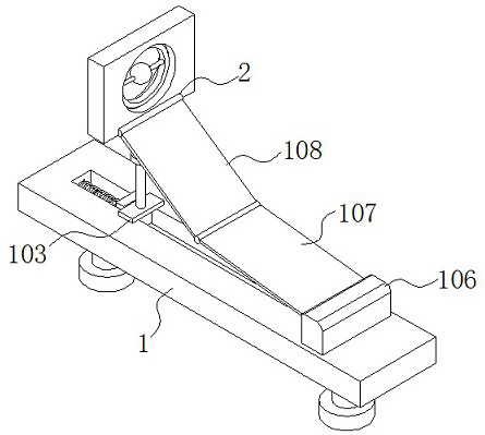
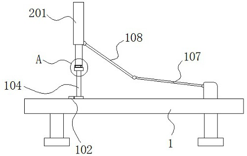
[0017] see Figure 1-5 , the present invention is an upper limb rehabilitation training equipment, comprising a fixed platform 1;

A limit chute 101 is provided on the upper surface of the fixing table 1; a push plate 102 is slidably connected inside the limit chute 101;

A slider is slidably fitted inside the limit chute 101, and a moving plate 103 is fixedly connected to the upper surface of the slider; one side of the moving plate...


PUM


Abstract

The invention discloses upper limb rehabilitation training equipment, and relates to the technical field of medical health training equipment. The device comprises a fixed table; limiting sliding grooves are formed in the upper surface of the fixing table. A push plate is slidably connected into the limiting sliding groove. One side of the moving plate is fixedly connected with one side of the push plate; the upper surface of the moving plate is fixedly connected with a threaded column; the upper end of the sleeve is fixedly connected with a training mechanism; supporting plates are fixedly connected to the upper surfaces of the fixing tables; a first supporting plate is hinged to one side face of the supporting plate. A second supporting plate is hinged to one side face of the first supporting plate. One side face of the second supporting plate is hinged to one side face of the training mechanism. Through the design of the limiting sliding groove, the spring, the first supporting plate, the second supporting plate and the training mechanism, in the upper limb rehabilitation training process of a patient, front-back stretching training and left-right rotating training of the upper limb can be achieved at the same time, the patient can obtain more comprehensive rehabilitation training, and the rehabilitation training effect is greatly improved.

Description

technical field [0002] The invention belongs to the technical field of medical and health training equipment, in particular to an upper limb rehabilitation training equipment. Background technique [0003] With the continuous development of medical technology, rehabilitation therapy has become a new therapeutic discipline that promotes the physical and mental recovery of patients and disabled persons, as well as a new technical specialty. Its purpose is to enable people to restore their ability to produce, study, work and labor, as well as social life as much as possible, integrate into society and improve their quality of life. Patients with upper limb loss of mobility and upper limb muscle atrophy due to cerebrovascular disease, brain trauma and other causes often rely on external passive exercise for rehabilitation training to help patients restore upper limb strength. [0004] The current upper limb rehabilitation training device generally cannot perform front and rear ...

Claims


Application Information

Patent Timeline
Patent Type & Authority Applications(China)
IPC IPC(8): A63B23/12
CPCA63B23/12
Inventor 沈周
Owner 常州江苏大学工程技术研究院
Why Eureka
Try Eureka