Tilt rotor unmanned aerial vehicle

A technology of tilting rotor and unmanned aerial vehicle, applied in the field of unmanned aerial vehicle, can solve the problem that fixed-wing flying mode and rotary-wing flying mode cannot coexist in the same unmanned aerial vehicle, etc., and achieve modular design, improved reliability, and simple operation. Effect

Inactive Publication Date: 2020-05-19
山东蜂巢航空科技有限公司
View PDF0 Cites 7 Cited by
  • Summary
  • Abstract
  • Description
  • Claims
  • Application Information

AI Technical Summary

Problems solved by technology

[0003] For this reason, the present invention provides a kind of tilt-rotor unmanned aerial vehicle, to solve the problem t

Method used


Image

  • Tilt rotor unmanned aerial vehicle
  • Tilt rotor unmanned aerial vehicle
  • Tilt rotor unmanned aerial vehicle

Examples


Embodiment 1

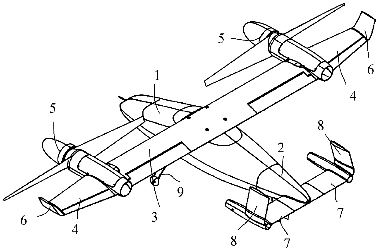
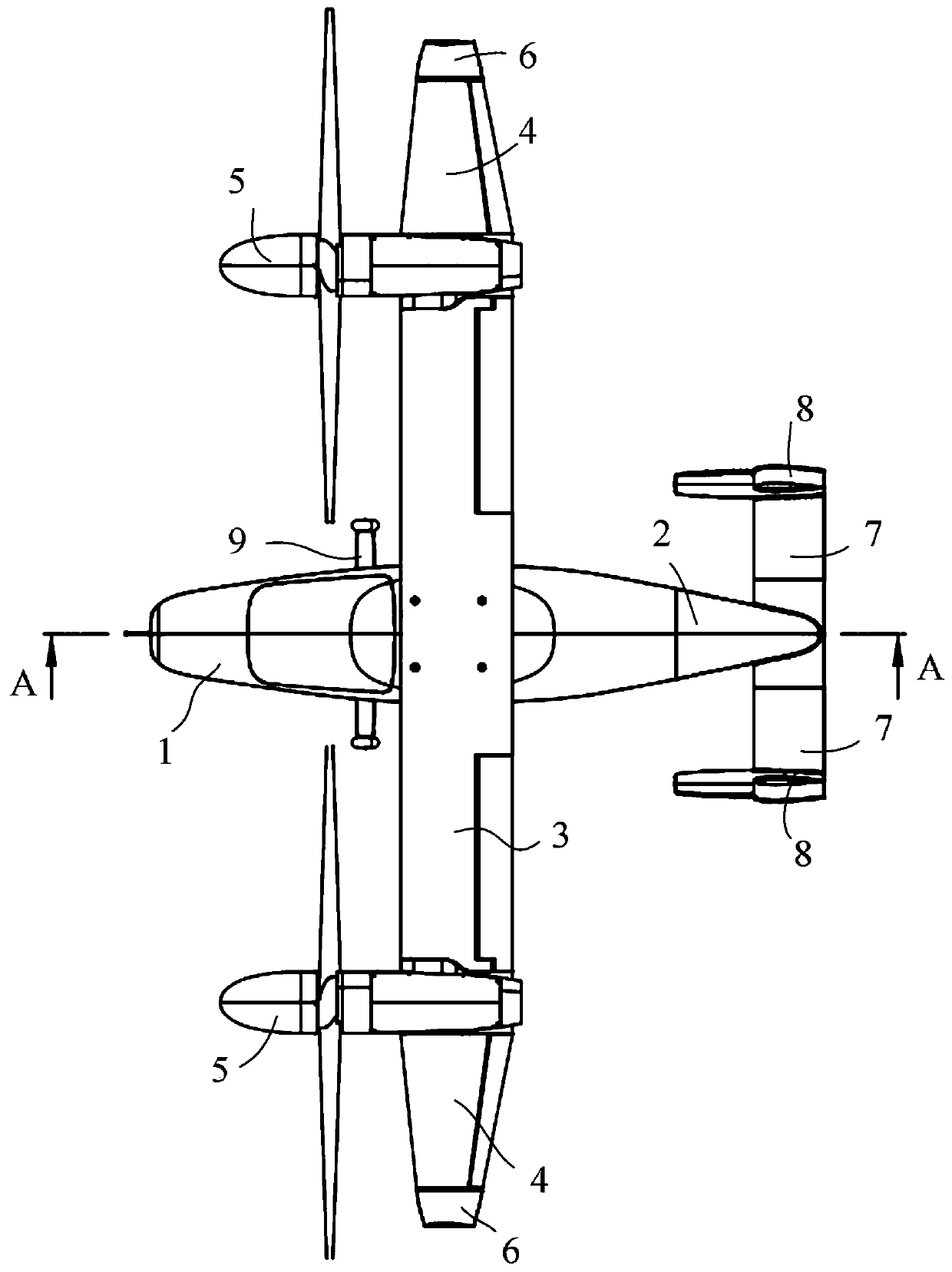
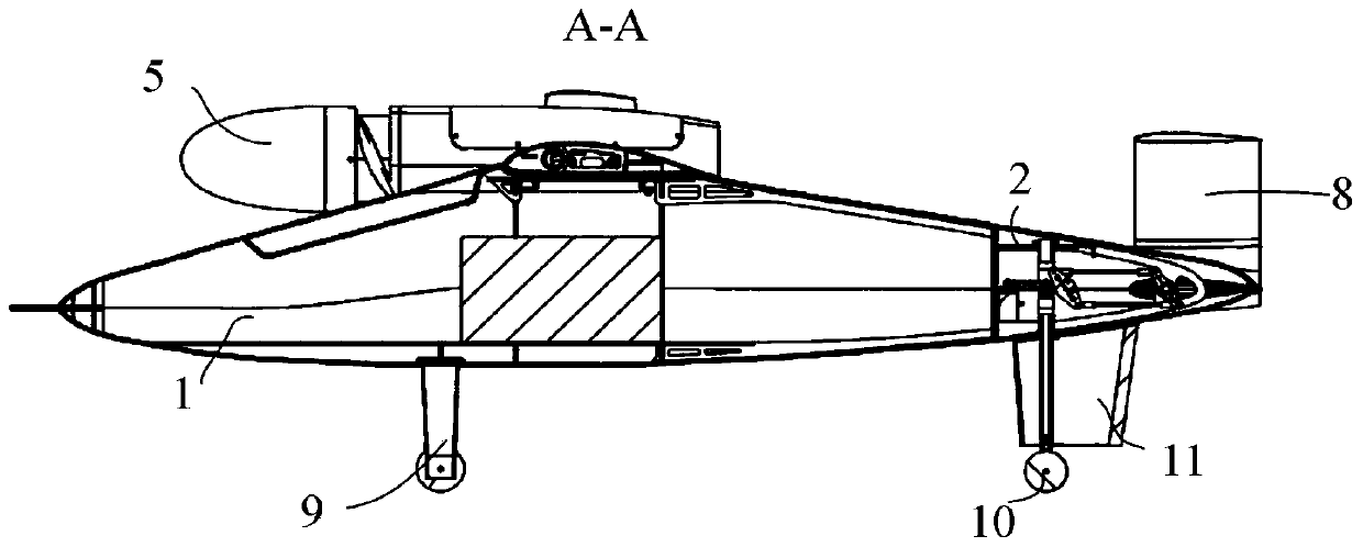
[0031] Such as Figure 1 to Figure 10 Shown, a kind of tilting rotor unmanned aerial vehicle among the present embodiment comprises front fuselage 1, rear fuselage 2, central wing 3, outer wing 4, propeller 5, drive motor 14, tilt steering gear 15 , the first swing assembly and the full-motion horizontal tail 7; the rear end of the front fuselage 1 is detachably connected with the front end of the rear fuselage 2, and the upper side of the front fuselage 1 is detachably connected with the central wing 3, and the central wing 3 The two ends are respectively rotated and connected with the outer wing 4, the outer wing 4 is provided with a driving motor 14, the output shaft of the driving motor 14 is provided with a propeller 5, and the outer wing 4 is provided with a tilting steering gear 15, and the tilting steering gear The rotating shaft of 15 is connected with the central wing 3 through the first swing assembly, and the tilt steering gear 15 drives the two outer wings 4 to sw...

Embodiment 2

[0035] Such as Figure 1 to Figure 10As shown, a tilt-rotor UAV in this embodiment includes all the technical features in Embodiment 1, in addition, it also includes the first beam 12, the motor frame 13 and the thrust bearing 19; the first The beam 12 is embedded and fixed in the central wing 3, and the two ends of the first beam 12 are located at the outer sides of the two ends of the central wing 3 respectively, and the motor frame 13 is connected to the first beam 12 by two thrust bearings 19 for rotation. The motor 14 is arranged on the front end of the motor frame 13, and the rear end of the motor frame 13 is provided with a tilting steering gear 15, and the rotating shaft of the tilting steering gear 15 is connected with the first beam 12 through the first swing assembly; the outer wing 4 is sleeved and fixed. On the outside of the motor frame 13; the first swing assembly includes a first rocker arm 16, a second rocker arm 18 and two first pull rods 17; , the middle pa...

Embodiment 3

[0039] Such as Figure 1 to Figure 10 Shown, a kind of tilting rotor unmanned aerial vehicle in the present embodiment includes all the technical features in Embodiment 2, in addition, also includes flat tail steering gear 21, the second swing assembly and the second beam 25; The steering gear 21 is fixedly arranged in the rear fuselage 2, the second beam 25 is embedded in the end of the rear fuselage 2 away from the front fuselage 1, and the second beam 25 is rotationally connected with the rear fuselage 2. The rotating shaft is connected with the second beam 25 through the second swing assembly, and the two ends of the second beam 25 are respectively fixed with a full-motion horizontal tail 7, and the two full-motion horizontal tails 7 of the horizontal tail steering gear 21 are switched between the horizontal rotation state and the vertical rotation state The rotating shaft of the flat tail steering gear 21 is arranged horizontally; the second swing assembly includes the th...


PUM

PropertyMeasurementUnit
Spanaaaaaaaaaa

Abstract

The invention discloses a tilt rotor unmanned aerial vehicle. The rear end of a front fuselage is detachably connected with the front end of a rear fuselage; the upper side of the front fuselage is detachably connected with a central wing; the two ends of the central wing are rotationally connected with outer wings correspondingly. A driving motor is arranged in the outer wing; propellers are arranged on output shafts of the driving motors, tilting steering engines are arranged in the outer wings, rotating shafts of the tilting steering engines are connected with the central wing through firstswinging assemblies, the tilting steering engines drive the two outer wings to be switched between a horizontal rotating state and a vertical rotating state, and two full-motion horizontal tails arearranged at the end, deviating from the front fuselage, of the rear fuselage; and the rotating shafts of the tilting steering engines are horizontally arranged. The purpose is to solve the problem that in the prior art, a fixed wing flight mode and a rotor wing flight mode cannot coexist on the same unmanned aerial vehicle. The tilt rotor unmanned aerial vehicle has the technical effects that vertical take-off and landing and horizontal high-speed direct flight can be achieved, vertical take-off and landing, rotor wing tilting and modular design are achieved, operation is easy, and reliabilityis remarkably improved.

Description

technical field [0001] The invention relates to the technical field of unmanned aerial vehicles, in particular to a tilt-rotor unmanned aerial vehicle. Background technique [0002] UAVs in the prior art mainly include rotary-wing UAVs and fixed-wing UAVs. Among them, the rotor UAVs have the advantages of vertical take-off and landing, flexible flight, etc., but the flight speed of the rotor UAVs is low and the battery life Relatively short; while the fixed-wing UAV has the advantages of fast flight speed and long battery life, but the fixed-wing UAV cannot take off and land vertically; it lacks an unmanned aerial vehicle that can take off and land vertically and can also take fixed-wing flight. man-machine. Contents of the invention [0003] Therefore, the present invention provides a tilt-rotor UAV to solve the problem in the prior art that the fixed-wing flight mode and the rotor flight mode cannot coexist on the same UAV. [0004] In order to achieve the above object...

Claims


Application Information

Patent Timeline
IPC IPC(8): B64C27/28B64C3/38B64C5/02B64C5/04B64C5/10B64C13/30
CPCB64C3/385B64C5/02B64C5/04B64C5/10B64C13/30B64C27/28
Inventor 李威尤冰冰冉德伟陈晨黄泽
Owner 山东蜂巢航空科技有限公司
Why Eureka
Try Eureka