Electrical power cable winding device for electric engineering

A technology of power cable and wire take-up device, which is applied in the field of electrical engineering, can solve the problem of not having to replace the winding reel, and achieve the effect of convenient operation

Inactive Publication Date: 2020-05-19
王丹丹
View PDF8 Cites 4 Cited by
  • Summary
  • Abstract
  • Description
  • Claims
  • Application Information

AI Technical Summary

Problems solved by technology

A cable winding device in the above-mentioned patent has the following disadvantages: it does not have the effect of facilitating the replacement of the winding reel. Therefore, it is urgent to design a power cable winding device for electrical engineering to solve the above problems

Method used


Image

  • Electrical power cable winding device for electric engineering
  • Electrical power cable winding device for electric engineering
  • Electrical power cable winding device for electric engineering

Examples


Embodiment 1

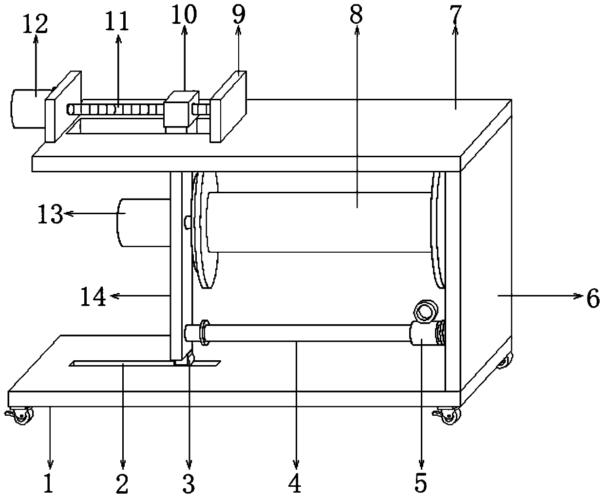
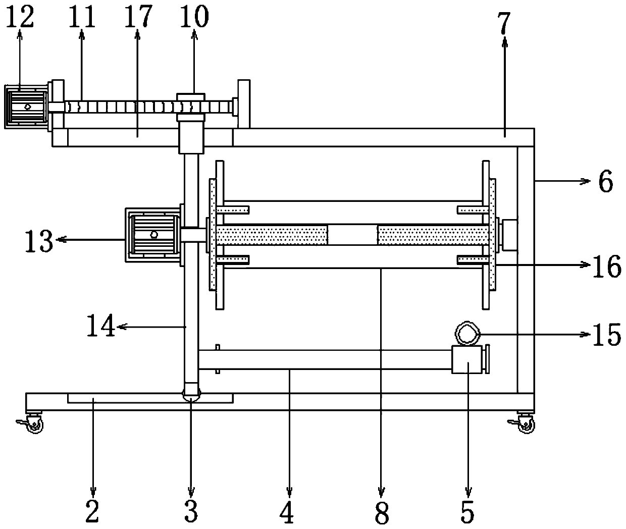
[0027] refer to Figure 1-3 , a power cable take-up device for electrical engineering, comprising a support base plate 1, a side plate 6 is welded to the top side of the support base plate 1, and a top plate 7 is welded to the top of the side plate 6, and the top end of the top plate 7 is connected to the top Both sides are welded with fixed seats 9, and one side of one of the fixed seats 9 is connected with a forward and reverse motor 12 by bolts, and the output shaft of the forward and reverse motors 12 is connected with a threaded lead screw 11 by bolts, and one end of the threaded lead screw 11 It is rotatably connected with one side of the other fixed seat 9, and the middle position of the top side of the top plate 7 has a second chute 17, and the outer wall of the threaded screw 11 is threaded with a movable sleeve 10, and the movable sleeve 10 The bottom is welded with a slider slidingly connected to the inner wall of the second chute 17, the bottom of the slider is wel...

Embodiment 2

[0035] refer to Figure 4 , a power cable take-up device for electrical engineering. Compared with Embodiment 1, this embodiment replaces the forward and reverse motor 12 with a handle 21, and the bottom of one side of the handle 21 is welded with a connecting rod, and the connecting rod One end passing through the fixing seat 9 is welded with one end of the threaded screw 11 .

[0036] Working principle: when in use, the user uses the turning handle 21 to drive the connecting rod to rotate in the fixed seat 9, to drive the threaded screw 11 to rotate, and to clamp and replace the winding reel 8 by manpower.


PUM


Abstract

The invention discloses an electrical power cable winding device for electric engineering. The electrical power cable winding device for electric engineering comprises a support bottom plate, whereina side plate is fixedly connected to one side of the top part of the support bottom plate; a top plate is fixedly connected to the top part of the side plate; fixed seats are fixedly connected to oneend of the top part and one side of the top part of the top plate; a positive and negative rotation motor is fixedly connected to one side of one fixed seat; a screw-thread lead screw is fixedly connected to an output shaft of the positive and negative rotation motor; one end of the screw-thread lead screw is rotatably connected with one side of the other fixed seat through a bearing; and a secondsliding chute is formed in the middle of one side of the top part of the top plate. According to the electrical power cable winding device for electric engineering provided by the invention, a winding plate is clamped between two extruding plates, the positive and negative rotation motor is utilized for driving a movable sleeve, a sliding block and a connecting plate to reset, and one extruding plate is separated from the winding plate, so that the winding plate is conveniently replaced; and a rotary motor is utilized for driving the winding plate to rotate, and the winding plate is utilizedfor winding cables.

Description

technical field [0001] The invention relates to the technical field of electrical engineering, in particular to a power cable take-up device for electrical engineering. Background technique [0002] Electrical engineering is one of the core disciplines in the field of modern science and technology, and it is also an indispensable key discipline in the field of high-tech electrical engineering. Power cables are one of the most commonly used workpieces in electrical engineering. [0003] After searching, the Chinese patent publication number is CN209161196U, which discloses a cable winding device, including a support platform, the top right side of the support platform is fixedly connected with a first vertical plate, and the left wall of the first vertical plate is Bearings are fixedly connected, the top left side of the support platform is fixedly connected with a second vertical plate, and the right wall of the second vertical plate is fixedly connected with a horizontal pl...

Claims


Application Information

Patent Timeline
Patent Type & Authority Applications(China)
IPC IPC(8): B65H75/40
CPCB65H75/403B65H2701/34
Inventor 王丹丹
Owner 王丹丹
Why Eureka
Try Eureka