High-strength special-shaped I-shaped steel

An I-beam, high-strength technology, applied in the direction of joists, girders, trusses, etc., can solve the problem of reducing the overall strength of I-beam, the poor bearing capacity of the end face of the transverse steel plate, and the low firmness of the connection between the transverse steel plate and the longitudinal steel plate. and other problems, to achieve the effect of improving convenience, improving compression effect, and reducing the probability of deformation

Pending Publication Date: 2021-03-30
凌燕凤
View PDF3 Cites 2 Cited by
  • Summary
  • Abstract
  • Description
  • Claims
  • Application Information

AI Technical Summary

Problems solved by technology

[0003] In the actual use of the traditional I-beam, its structure is simple, the firmness of the connection between the transverse steel plate and the longitudinal steel plate is low, and the pressure bearing capacity of the entire end face of the transverse steel plate is poor, which greatly reduces the overall strength of the I-beam. In this regard, it is necessary to design a high-strength special-shaped I-beam

Method used


Image

  • High-strength special-shaped I-shaped steel
  • High-strength special-shaped I-shaped steel
  • High-strength special-shaped I-shaped steel

Examples


Embodiment Construction

[0027] In order to make the technical means, creative features, goals and effects achieved by the present invention easy to understand, the present invention will be further described below in conjunction with specific embodiments.

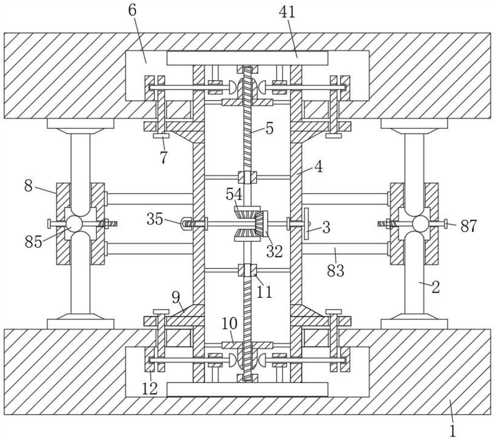
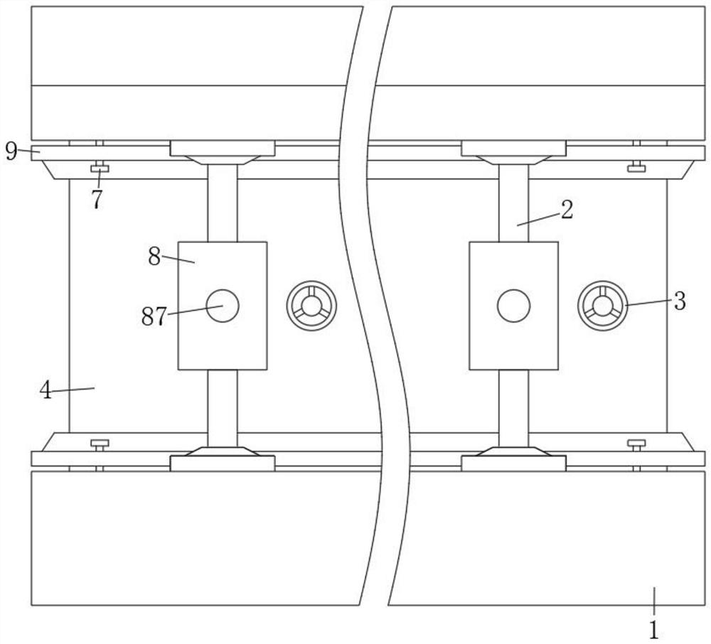
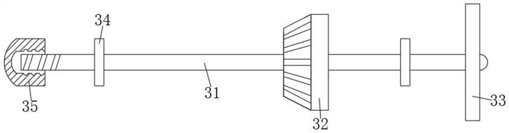
[0028] like Figure 1-Figure 9As shown, a high-strength special-shaped I-beam according to the present invention includes two horizontal steel plates 1 arranged in parallel, a longitudinal steel plate 4 is fixedly installed between the two horizontal steel plates 1, and both horizontal steel plates 1 are excavated There is a first cavity 6, and the two ends of the longitudinal steel plate 4 are inserted into the matched first cavity 6 and fixedly connected with the inner wall of the cavity, and the two outer walls of the longitudinal steel plate 4 are fixedly installed with several Reinforcement assembly 8, a number of reinforcement rods 2 are fixedly installed on the opposite inner walls of the two transverse steel plates 1, and the ends of the t...


PUM


Abstract

The invention relates to the field of I-shaped steel, and particularly relates to high-strength special-shaped I-shaped steel. The high-strength special-shaped I-shaped steel comprises two transversesteel plates arranged in parallel, wherein a longitudinal steel plate is fixedly installed between the two transverse steel plates; a plurality of reinforcing assemblies are fixedly installed on the two outer walls, away from each other, of the longitudinal steel plate; a plurality of reinforcing rods are fixedly installed on the opposite inner walls of the two transverse steel plates; two reinforcing sleeve plates are symmetrically connected to the outer wall of the longitudinal steel plate in a sleeving mode; a plurality of inserting drill rods are movably installed on the two reinforcing sleeve plates; a plurality of limiting mechanisms are fixedly installed between the inner walls of the longitudinal steel plate; a plurality of locking mechanisms are symmetrically and fixedly installedin two first cavities; and the plurality of locking mechanisms are connected with the inserting drill rods arranged in a matched mode in a clamped mode. According to the I-shaped steel, the joints ofthe transverse steel plates and the longitudinal steel plate are reinforced, the pressure bearing capacity of the whole outer end faces of the transverse steel plates is enhanced, the pressure resistance effect of the transverse steel plates is effectively improved, the probability of deformation generated after pressure bearing is reduced, and the overall strength of the transverse steel platesis greatly improved.

Description

technical field [0001] The invention relates to the field of I-beams, in particular to a high-strength special-shaped I-beam. Background technique [0002] I-beam, also known as steel beam, is a long strip of steel with an I-shaped cross section. I-shaped steel is divided into hot-rolled I-beam and light I-beam. The horizontal steel plate and a longitudinal steel plate are composed together. I-beams are mainly divided into three types: ordinary I-beams, light I-beams, and low-alloy light I-beams. Ordinary I-beams and light I-beams have relatively Higher and narrower, so the moment of inertia of the two main sleeves on the cross-section differs greatly, which limits its application range. The use of I-beams should be selected according to the requirements of the design drawings. Channel steel It is mainly used in building structure, curtain wall engineering, mechanical equipment and vehicle manufacturing, etc. It is required to have good welding, riveting performance and com...

Claims


Application Information

Patent Timeline
Patent Type & Authority Applications(China)
IPC IPC(8): E04C3/04
CPCE04C3/04E04C2003/0452
Inventor 凌燕凤左延鹏
Owner 凌燕凤
Why Eureka
Try Eureka