Double-stator staggered rotor tooth flux switching type permanent magnet motor and electromagnetic equipment

A technology of magnetic flux switching and permanent magnet motor, which is applied to magnetic circuits, electromechanical devices, electrical components, etc. Increase the difficulty of manufacturing and other issues to achieve the effects of high fault tolerance, improved winding coefficient, and high bearing capacity

Pending Publication Date: 2020-05-19
SHANDONG UNIV
View PDF5 Cites 0 Cited by
  • Summary
  • Abstract
  • Description
  • Claims
  • Application Information

AI Technical Summary

Problems solved by technology

Even so, due to the double salient pole structure of this type of motor, the motor has the disadvantages of high cogging torque and torque ripple, which inevitably produces vibration and noise
[0005] The inventors found that although the cogging torque and torque ripple can be reduced to a certain extent by cutting permanent magnets, oblique pole chute, optimizing tooth shape or adopting complex driving algorithms, it will inevitably lead to a decline in output torque And it increases the difficulty of manufacturing. Therefore, the existing flux switching permanent magnet motor has the problem of inconsistency between torque density improvement and torque ripple suppression.

Method used


Image

  • Double-stator staggered rotor tooth flux switching type permanent magnet motor and electromagnetic equipment
  • Double-stator staggered rotor tooth flux switching type permanent magnet motor and electromagnetic equipment
  • Double-stator staggered rotor tooth flux switching type permanent magnet motor and electromagnetic equipment

Examples


Embodiment 1

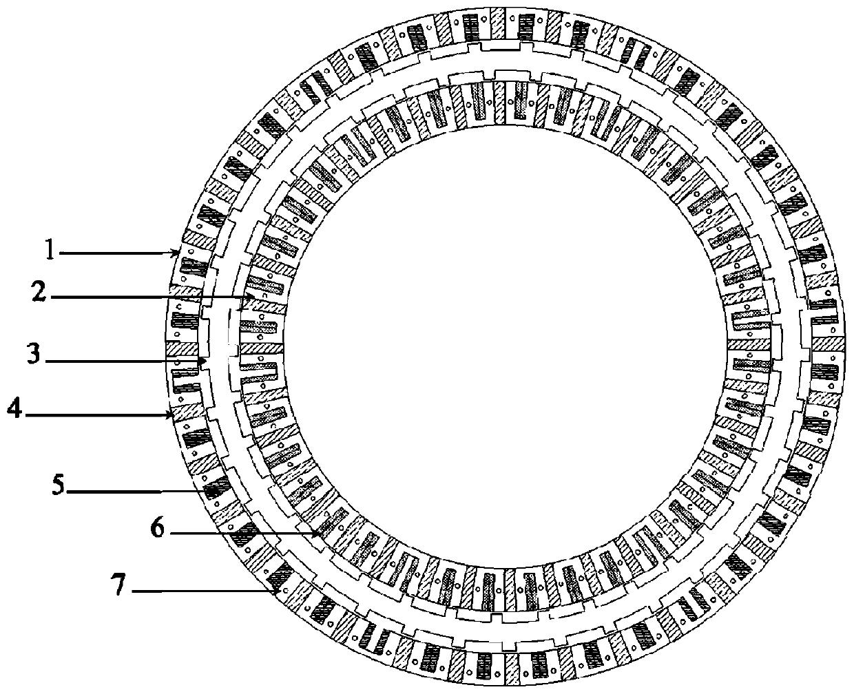
[0049] Such as figure 1 As shown, a flux-switching permanent magnet motor with double stators and rotor teeth in this embodiment includes an inner stator, an outer stator and a rotor.

[0050] Wherein, the inner stator is arranged inside the rotor 3; the inner stator includes the inner stator U-shaped core unit 2, the inner stator permanent magnet and the inner stator winding 6; the outer stator is arranged outside the rotor 3; the outer stator includes the outer stator U-shaped iron core unit 1, Outer stator permanent magnets 4 and outer stator windings 5 ​​. Both the outer stator winding 5 and the inner stator winding 6 adopt multi-coil phase-group concentrated windings, which can be independently controlled; the inner stator permanent magnets are arranged between two adjacent inner stator U-shaped core units, and are closely attached to each other. installed; the stator permanent magnets are set between two adjacent stator U-shaped core units and are closely mounted. Both...

Embodiment 2

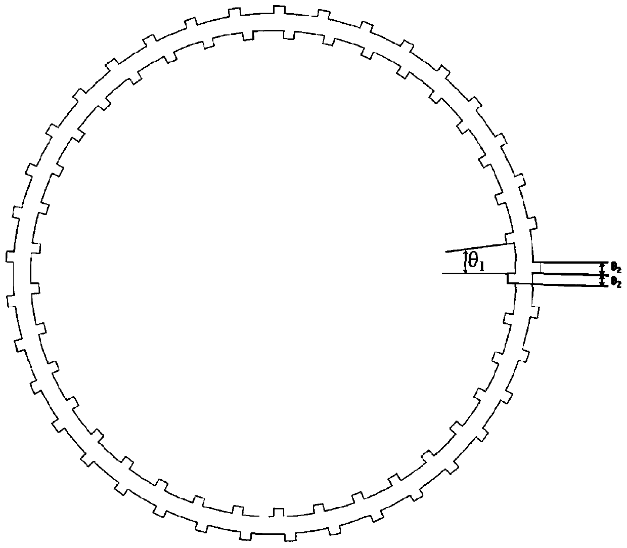
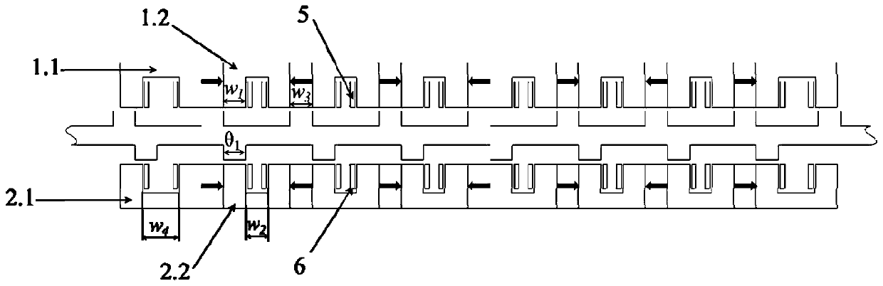
[0067] This embodiment provides the electromagnetic equipment as described in Embodiment 1, the electromagnetic equipment includes a double-stator dislocation rotor tooth flux switching permanent magnet motor, which adopts the dislocation arrangement structure of the inner rotor teeth and the outer rotor teeth to realize the permanent magnet flux The alternating polymerization on the inner and outer air gaps improves the torque density, and effectively suppresses torque ripple through the superposition of torque components generated by the double air gaps.


PUM


Abstract

The invention belongs to the field of motor design and manufacturing, and provides a double-stator staggered rotor tooth flux switching type permanent magnet motor and electromagnetic equipment, whichsolve the problem that an existing flux switching type permanent magnet motor is not coordinated in torque density improvement and torque ripple suppression, and have the effects of being high in power density, high in overload capacity, low in cogging torque, low in torque ripple and suitable for modular manufacturing. The motor comprises an inner stator arranged inside the rotor, an outer stator disposed outside the rotor, and a rotor with the inner side and the outer side respectively and uniformly provided with a plurality of inner side rotor teeth and outer side rotor teeth. The inner side rotor teeth and the outer side rotor teeth are arranged in a staggered manner, so that the permanent magnetic flux is alternately aggregated on the inner and outer side air gaps of the rotor to improve the torque density, and the torque pulsation is inhibited through torque component superposition generated by the inner and outer side air gaps of the rotor.

Description

technical field [0001] The invention belongs to the field of motor design and manufacture, and in particular relates to a double-stator dislocation rotor tooth magnetic flux switching permanent magnet motor and electromagnetic equipment. Background technique [0002] The statements in this section merely provide background information related to the present invention and do not necessarily constitute prior art. [0003] According to the different placement positions of the permanent magnets of the permanent magnet motor, the permanent magnet motor can be classified into a permanent magnet stator type motor and a permanent magnet rotor type motor. The permanent magnet stator type motor refers to placing the permanent magnet on the motor stator, and the permanent magnet rotor type motor refers to placing the permanent magnet on the rotor. In current industrial applications, permanent magnet rotor motors dominate. According to the different placement of permanent magnets on t...

Claims


Application Information

Patent Timeline
Patent Type & Authority Applications(China)
IPC IPC(8): H02K1/22H02K1/24H02K1/17H02K1/14H02K3/18H02K3/28H02K16/04H02K29/03
CPCH02K1/22H02K1/24H02K1/17H02K1/143H02K3/18H02K3/28H02K16/04H02K29/03H02K2201/03
Inventor 赵文良虞铭杰张利勃王秀和
Owner SHANDONG UNIV
Why Eureka
Try Eureka