Novel inner rotor permanent magnet motor

A technology of inner rotor motor and inner rotor, which is applied to synchronous motors with stationary armatures and rotating magnets, magnetic circuits, electrical components, etc. High winding coefficient, low harmonic coefficient, and the effect of ensuring high-efficiency operation

Active Publication Date: 2012-11-21
FANS TECH ELECTRIC CO LTD
View PDF0 Cites 0 Cited by
  • Summary
  • Abstract
  • Description
  • Claims
  • Application Information

AI Technical Summary

Problems solved by technology

[0004] For example, when an internal rotor motor is applied to an axial flow fan, there is a problem of unsatisfactory efficiency in the application, and the main reason for this problem is that the operating frequency of the motor is low, only tens of hertz, while the general permanent magnet synchronous motor is ideal The operating frequency is between 150-250 Hz, but since the speed of the motor cannot be changed, the number of paired permanent magnet poles of the rotor can only be increased. At a speed of about 1000 rpm, the number of poles of the motor must be greater than 20 poles. According to the traditional design method of the motor The number of slots of the stator must also be increased to more than 20 slots, which makes the overall processability of the motor poor, and its winding coefficient is low

Method used


Image

  • Novel inner rotor permanent magnet motor
  • Novel inner rotor permanent magnet motor
  • Novel inner rotor permanent magnet motor

Examples


Embodiment Construction

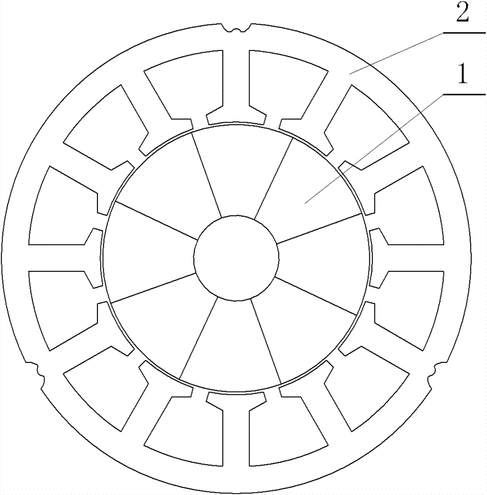
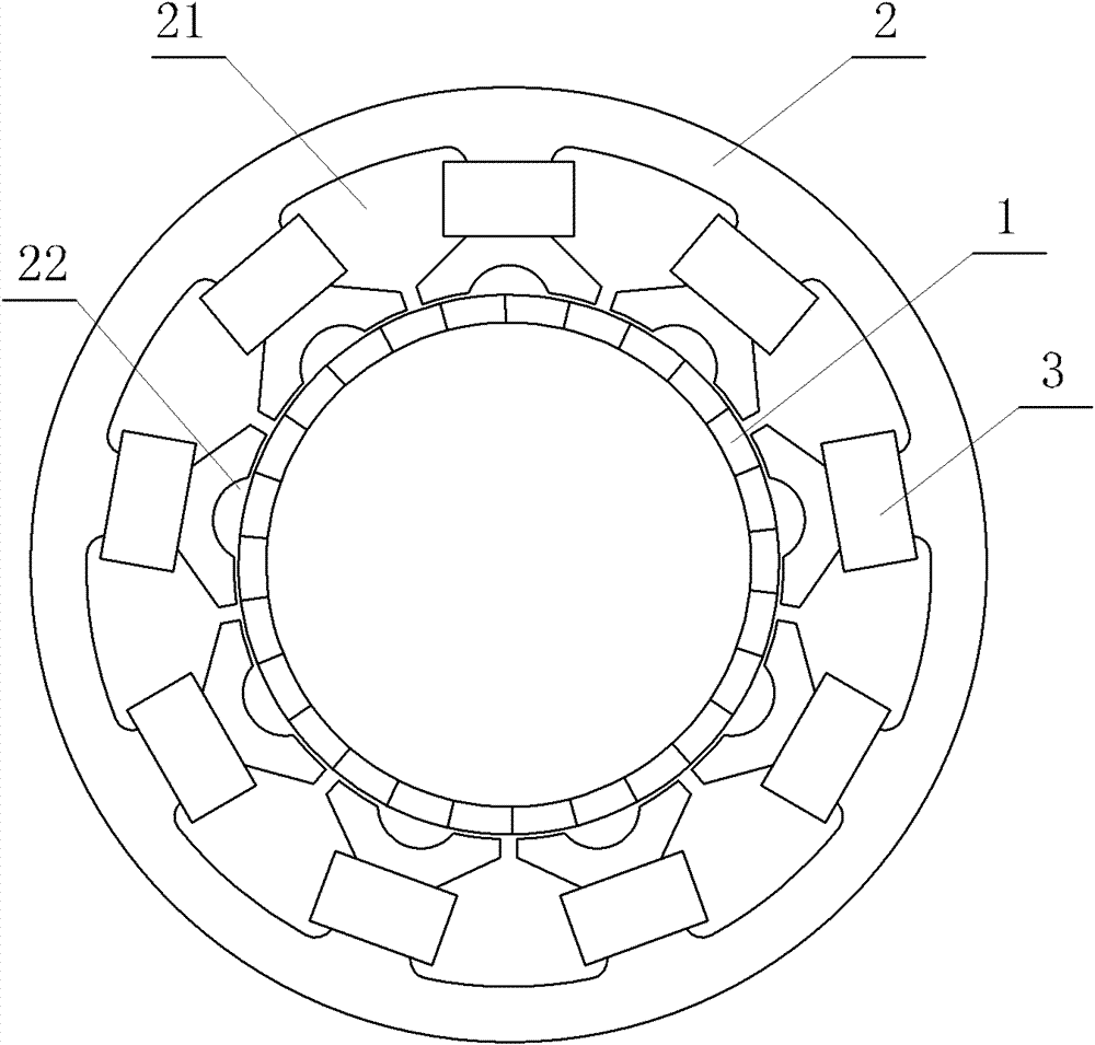
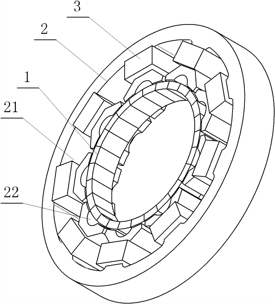
[0017] Such as figure 2 , image 3 As shown, the permanent magnet inner rotor motor according to the present invention includes a stator assembly and a shaft-type inner rotor 1 placed inside, and the stator assembly includes a stator core 2 and a stator coil 3 wound on the stator core 2 , the stator core 2 is a fractional slot design in which the ratio of the number of slots of the large slot 21 of the stator core to the number of poles of the paired permanent magnets of the rotor 1 is a fraction, and the number of poles of the large slot 21 and the rotor 1 The ratio satisfies ((2p±1) / 3): 2p, where p is the number of motor pole pairs, and the top of each tooth of the stator core 2 is correspondingly provided with a small slot 4, which greatly reduces the motor stator The influence of the reverse magnetic field makes the number of slots per pole and phase of the motor q=(2p±1) / 6p=1 / 3±1 / 6p. When p=13 (26 poles), q=26 / 27, the harmonic coefficient is extremely low.

[0018] In...


PUM


Abstract

The invention belongs to the technical field of motors, and in particular relates to a novel inner rotor permanent magnet motor with permanent magnet. The inner rotor permanent magnet motor comprises a stator assembly and a shaft type inner rotor inside the inner rotor, wherein the rotor assembly comprises a stator iron core and a stator coil which is wound on the stator iron core; the stator iron core is of a big and small slot structure which comprises big slots and small slots; the number of the small slots is equal to the number of the big slots; the small slots are correspondingly distributed on the top of the each tooth of the stator iron core; the ratio of the number of the big slots to the number of poles of the rotor is in a fractional slot design; the ratio of the number of the big slots to the number of poles of the rotor meets the following formula: the ratio is equal to (2p+ / -1) / 3: 2p, wherein p represents pole pairs of the motor; and the total number of the stator iron core is (2p+ / -1) / 3*2. On the basis of keeping higher processing property, slot insulation materials of the inner rotor permanent magnet motor are reduced, the winding coefficients are high, the harmonic content is small and the efficient running of the motor can be ensured. The inner rotor permanent magnet motor can be widely applied to an axial flow fan and other electrical equipment, thus ensuring preferable usability of the axial flow fan and the other electrical equipment.

Description

technical field [0001] The invention belongs to the technical field of motor products. Specifically disclosed is a novel permanent magnet inner rotor synchronous motor. Background technique [0002] Most of the existing permanent magnet inner rotor motors are in the form of concentrated winding, such as figure 1 As shown, the permanent magnet inner rotor motor includes a stator 2 and a rotor 1, the ratio of the number of slots of the stator 2 to the number of paired permanent magnet poles of the rotor 1 is 3:2, for example, for a typical 8-pole motor, the stator 2 It is a structure of 12 stator slots. [0003] When the motor runs below 1000 rpm, the efficiency of the motor is significantly lower than that of the motor above 1000 rpm, and the frequency of the motor's operation is only tens of Hz. [0004] For example, when an internal rotor motor is applied to an axial flow fan, there is a problem of unsatisfactory efficiency in the application, and the main reason for thi...

Claims


Application Information

Patent Timeline
Patent Type & Authority Patents(China)
IPC IPC(8): H02K21/14H02K1/16H02K1/14
CPCH02K1/16H02K21/16H02K21/14H02K1/146H02K1/14
Inventor 夏传富林敏萍
Owner FANS TECH ELECTRIC CO LTD
Why Eureka
Try Eureka