
Radial and axial dual-modular magnetic flux switching motor

A magnetic flux switching motor, dual-module technology, applied in the direction of magnetic circuits, electric components, electromechanical devices, etc., can solve the problems of low winding factor, low end space utilization, poor motor output performance, etc., to improve the surface heat dissipation coefficient , Inhibit the temperature rise, the effect of inhibiting the unilateral magnetic pull

Active Publication Date: 2021-07-27
HEBEI UNIV OF TECH
View PDF15 Cites 0 Cited by
  • Summary
  • Abstract
  • Description
  • Claims
  • Application Information

AI Technical Summary

Problems solved by technology

[0003] At present, the winding factor of the armature winding of the traditional 6-slot / 5-pole flux switching permanent magnet motor is low, and the harmonic content in the permanent magnet flux linkage is relatively large, and the sine of the harmonic is poor, resulting in poor output performance of the motor. Poor, cannot well meet the changing needs of the motor operating environment
[0004] The Chinese patent with the publication number CN111211659A proposes a dual-stator permanent magnet motor with stator modular ring winding. The stator is located between the inner rotor and the outer rotor. The inner rotor and the outer rotor respectively form independent air gaps with the stator. It overcomes the problems of long end windings, large copper consumption and low end space utilization of traditional stator permanent magnet motors, and effectively improves the efficiency of the motor; the motor adopts a double-rotor structure in the radial direction, and the space between the two rotors and the stator The air gap magnetic flux density cannot cancel each other out, and thus the odd harmonics cannot be eliminated, resulting in poor sinusoidality of the permanent magnet flux linkage harmonics

Method used


Image

  • Radial and axial dual-modular magnetic flux switching motor
  • Radial and axial dual-modular magnetic flux switching motor
  • Radial and axial dual-modular magnetic flux switching motor

Examples


Embodiment Construction

[0027] The technical solutions of the present invention will be described in detail below in conjunction with the embodiments and drawings, which are not intended to limit the protection scope of the present application.

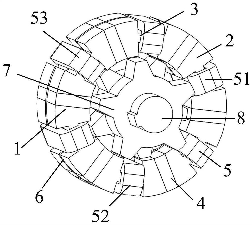
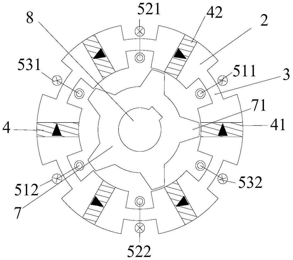
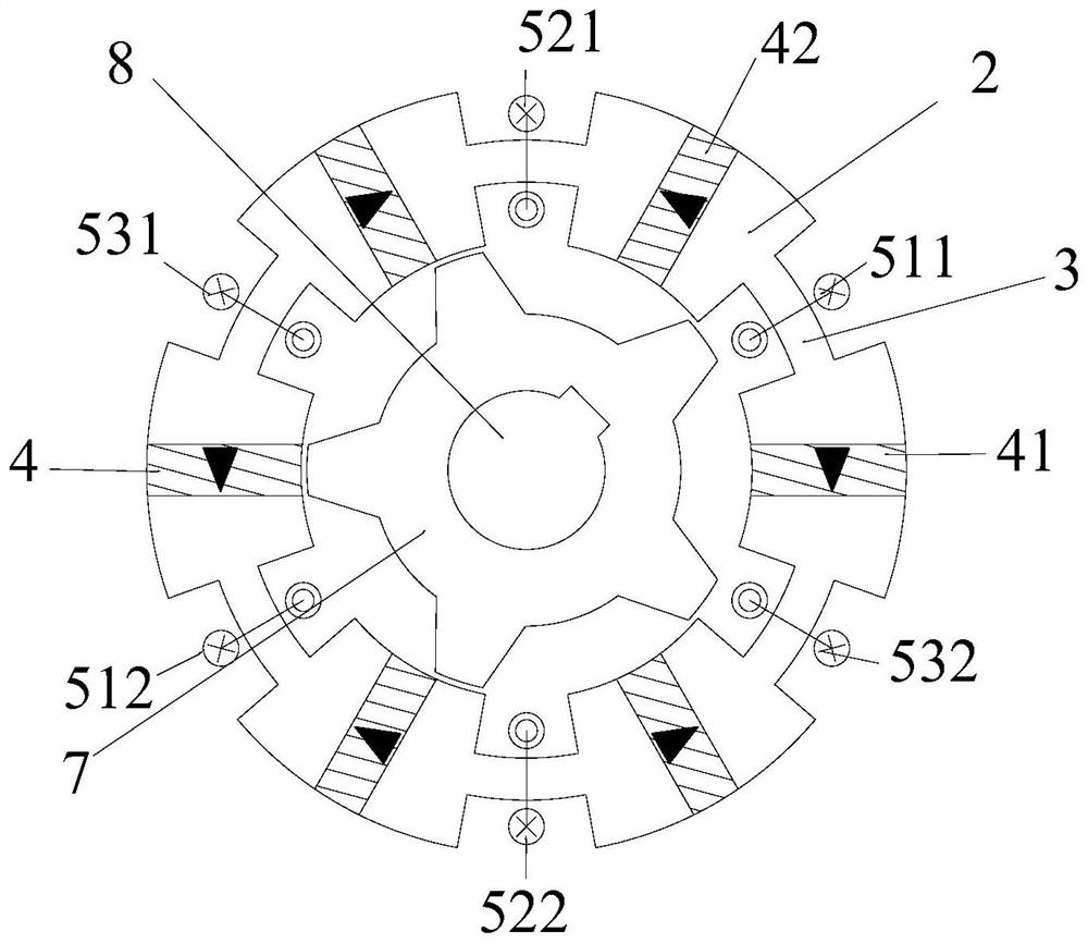
[0028] like figure 1 As shown, the present invention is a radial and axial dual modular flux switching motor (referred to as motor), including a stator and a rotor; the stator includes armature windings 5 ​​and at least one axially arranged stator module, each The stator module includes two stator units 1, and a magnetic isolation ring 6 is embedded between the two stator units 1 of each stator module and between the two adjacent stator units 1 of two adjacent stator modules; each stator unit 1 includes permanent magnets 4 and a plurality of circumferentially arranged stator cores 2, permanent magnets 4 are embedded between two adjacent stator cores 2, and the magnetization direction of the permanent magnets 4 is tangential. The magnetization directions of ...


PUM


Abstract

The invention relates to a radial and axial dual-modular magnetic flux switching motor. The radial and axial dual-modular magnetic flux switching motor comprises a stator and a rotor; the stator comprises an armature winding and at least one stator module arranged in the axial direction, each stator module comprises two stator units, and magnetic isolation rings are embedded between the two stator units of each stator module and between the two adjacent stator units of the two adjacent stator modules; each stator unit comprises a permanent magnet and a plurality of stator iron cores which are arranged in a circumferential manner, and the permanent magnet is embedded between two adjacent stator iron cores; the same armature coil of the armature winding is wound on the magnetic conductive bridge arms of the stator cores at the same positions of all the stator units along the axial direction of the motor; and the rotor comprises rotor modules with the same number as the stator modules, each rotor module comprises two rotor units, and the difference between the central angles of the installation positions of the two rotor units of each rotor module is 180 DEG. The harmonic waveform of the permanent magnet flux linkage of the motor is closer to sine waves, pulsation of output torque of the motor is reduced, and vibration and noise are reduced.

Description

technical field [0001] The invention is a modular brushless motor based on the principle of magnetic flux switching, in particular to a radial and axial dual modular magnetic flux switching motor, which belongs to the technical field of motor manufacturing. Background technique [0002] In the fields of wind power generation, new energy electric vehicles, industrial technology, aircraft, shipbuilding and other fields, not only the motors are required to have good torque and speed characteristics to meet the changing conditions of equipment operating conditions, but also the operating efficiency of the motor system and Reliability is in high demand. The stator permanent magnet flux switching motor has the advantages of high torque (power) density, strong torque output capability, and high efficiency, and is widely used in various working conditions. The permanent magnets and armature windings of the flux switching motor are placed on the stator side, which is easy to cool an...

Claims


Application Information

Patent Timeline
Patent Type & Authority Applications(China)
IPC IPC(8): H02K1/14H02K3/52H02K1/17H02K1/24H02K16/00
CPCH02K1/141H02K1/148H02K3/522H02K1/17H02K1/24H02K16/00H02K2201/03H02K2213/03H02K2213/12
Inventor 苏鹏王一维申怡李永建胡艳芳
Owner HEBEI UNIV OF TECH
Learn More