Brushless double-fed motor wound rotor winding and manufacturing method thereof

A technology of wound rotor and doubly-fed motor, applied in electric components, asynchronous induction motors, manufacturing of motor generators, etc., can solve the problems of large harmonic content of rotor windings, affecting winding performance, and complex process.

Active Publication Date: 2014-04-09
HUAZHONG UNIV OF SCI & TECH +1
View PDF4 Cites 0 Cited by
  • Summary
  • Abstract
  • Description
  • Claims
  • Application Information

AI Technical Summary

Problems solved by technology

[0005] Regarding the wound rotor winding of brushless doubly-fed motors, Chinese patent ZL200710051768.1 discloses a wound rotor winding of brushless doubly-fed motors. The two fundamental wave pole-pair numbers p 1 and p 2 The winding factor is high, but because of the small number of rotor slots, the harmonic content of the rotor winding is too large, which affects the winding performance; another Chinese patent ZL200910061297.1 discloses another brushless doubly-fed motor wound rotor Winding, its performance has been improved, and the high-order harmonic content can be small, but there are multiple turns of the coil, the process is complicated, and the number of pole pairs of the two fundamental waves p 1 and p 2 It is difficult to adjust the relative winding coefficient, and the utilization rate of winding layout space is low.

Method used


Image

  • Brushless double-fed motor wound rotor winding and manufacturing method thereof
  • Brushless double-fed motor wound rotor winding and manufacturing method thereof

Examples


Embodiment 1

[0024] There is a brushless doubly-fed motor rotor, where p 1 =2, p 2 =4, z=54, a wound rotor winding scheme composed of two sets of multi-phase sub-windings superimposed.

[0025] According to the above method, the number of phases is m=p 1 +p 2 =2+4=6, the number of basic slots per phase z φ =z / m=54 / 6=9.

[0026] First consider the first set of sub-windings. Assume that the sub-winding is a double-layer winding, because each phase is composed of serially numbered coils, if the number of coils is n 1 =z φ =9, its corresponding phase bandwidth, although for p 1 =2 may be appropriate, but for p 2 =4 may be too large, which will cause p 2 =5 The winding coefficient is too low, so some coils must be removed. As for how much to remove, and the coil pitch y 1 , It can be decided after harmonic analysis. Take n here 1 =6φ =9, and y 1 = 7. And because the number of phases m=6, the winding space of each phase differs by 2π / m mechanical angle in turn, so you can use the slot number phase d...

Embodiment 2

[0029] A brushless doubly-fed motor rotor, p 1 =2, p 2 =4, z=84, a wound rotor winding scheme composed of two sets of multiphase sub-windings superimposed.

[0030] According to the above method, the number of phases is m=p 1 +p 2 =2+4=6, the number of basic slots per phase z φ =z / m=84 / 6=14.

[0031] A scheme for the arrangement of coil slot numbers, for the first set of sub-windings, take n 1 =9, and y 1 =12, the slot number of each phase coil at this time is: A 11 Phase (1, 2, 3, 4, 5, 6, 7, 8, 9); A 12 Phase (43, 44, 45, 46, 47, 48, 49, 50, 51); B 11 Phase (15, 16, 17, 18, 19, 20, 21, 22, 23); B 12 Phase (57, 58, 59, 60, 61, 62, 63, 64, 65); C 11 Phase (29, 30, 31, 32, 33, 34, 35, 36, 37); C 12 Phase (71, 72, 73, 74, 75, 76, 77, 78, 79).

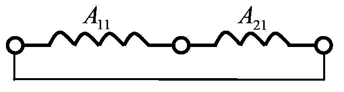
[0032] For the second set of sub-windings, because it is a single-layer winding, if the coil pitch is y 2 =9, the number of coil slots should be: n 2 =z / (p 1 +p 2 )-y 2 =84 / (2+4)-9=5, the slot number of each phase coil can be taken as: A 21 Phase...


PUM


Abstract

The invention relates to a brushless double-fed motor wound rotor winding and a manufacturing method thereof, and adopts two sets of multiphase sub windings to form a multiphase winding type winding in a stacking and overlapping way. The two sets of multiphase sub windings are respectively comprise coils and pitches, wherein the numbers of the coils and the numbers of the pitches of the two sets are respectively different, one of the two sets of multiphase sub windings comprises m phases of sub windings, each phase the m phases of sub windings is composed of n 1 serial-connection coils which have N1 turns and are numbered in order or is in a double-layer or a single-layer manner, and a coil pitch is y1; the other set of m phases of sub windings is in a single-layer manner, each phase is composed of n 2 serial-connection coils which have N2 turns and are numbered in order, a coil pitch is y 2, and the n 2 and the y 2 meet a relation that n2= z / (p1+p2)-y2; after the two sets of multiphase sub windings are synthetized, the all coils (in each phase) n= n 1+ n 2 are successively connected in series and then are connected from a short circuit, and the relative positions of the two sets of multiphase sub windings is shifted through regulating the numbers pitches or relative turns of the coils; and the optimum matching is realized so as to generate a superimposed effect, thereby achieving the purpose of improving fundamental wave utilization ratio of a winding coil conductor and weakening a harmonic wave.

Description

Technical field [0001] The invention relates to a wound rotor winding of a brushless double-fed motor and a manufacturing method. Background technique [0002] AC brushless doubly-fed motors are suitable for variable frequency speed regulation systems, and are characterized by reliable operation and small required inverter capacity. There are two sets of windings on the stator of this motor, and the number of pole pairs is p 1 , Another set of pole pairs is p 2 . When the stator winding p 1 Turn on the power grid, the number of pole pairs generated is p 1 The rotating magnetic field, the induced current in the rotor produces p 1 In addition to the polar magnetic field, p 2 For the pole magnetic field, the two pole logarithmic magnetic fields have opposite rotation directions relative to the rotor. For example, in the stator p 2 The winding is connected to a variable frequency power supply, and the motor speed can be changed by changing the frequency of the variable frequency po...

Claims


Application Information

Patent Timeline
Patent Type & Authority Patents(China)
IPC IPC(8): H02K17/14H02K3/28H02K15/09
Inventor 王雪帆赵文成
Owner HUAZHONG UNIV OF SCI & TECH
Why Eureka
Try Eureka