Multi-phase nested winding permanent magnet synchronous planar motor
A planar motor, permanent magnet synchronous technology, applied in electrical components, electromechanical devices, electric components, etc., can solve the problem of low utilization rate of winding coefficients, and achieve the effect of reducing control difficulty, removing electromagnetic attraction, and reducing end length.
- Summary
- Abstract
- Description
- Claims
- Application Information
AI Technical Summary
Problems solved by technology
Method used
Image
Examples
Embodiment 1
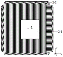
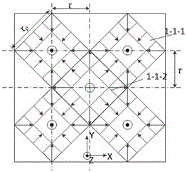
[0034] Such as figure 1 with figure 2 As shown, the multi-phase nested winding type permanent magnet synchronous planar motor described in this embodiment includes a permanent magnet excitation part 1 and an orthogonal nested armature winding part 2, both of which are planar structures with an air gap in the middle ; In the planar motor, the permanent magnet excitation part 1 is the mover, and the armature winding part 2 is the stator. The side length and the number of poles of the stator are larger than the mover, and the difference between the side length and the number of poles of the two determines the driving range of the planar motor. The permanent magnet excitation part 1 includes two parts: a two-dimensional permanent magnet array 1-1 and a yoke 1-2. The two-dimensional permanent magnet array 1-1 is pasted on the surface of the yoke 1-2 near the winding side; the armature The winding 2 includes two sets of windings, one set is the winding 2-1 placed along the X direc...
Embodiment 2
[0042] The difference between this embodiment and Embodiment 1 is that in the multi-phase nested winding type permanent magnet synchronous planar motor, the permanent magnet excitation part 1 is the stator, and the armature winding part 2 is the mover. The structure of the armature winding 2 is relatively simple, eliminating the need for a thyristor structure. The winding 2-1 placed in the X direction and the winding 2-2 placed in the Y direction are directly divided into 4 parts with the center line of the Y direction and the X direction as the dividing line; the number of poles in each part is 2n, where n is an integer , the total number of poles of all windings is 8n; the same-phase windings in each part are connected to each other.
Embodiment 3
[0044] The difference between this embodiment and Embodiments 1-2 is: as Image 6 As shown, the magnetization direction of the auxiliary magnetic pole 1-1-1-2 at the side of the N-pole excitation module and the auxiliary magnetic pole 1-1-2-2 at the side of the S-pole excitation module are magnetized in parallel It becomes magnetized in the diagonal direction. The auxiliary magnetic pole 1-1-1-2 on the side of the N-pole excitation module is magnetized in the direction from the winding side close to the central part to the yoke side close to the outside, and at the same time contains the direction from the S pole to the N pole and the vertical The magnetic field component facing outward from the plane of the yoke; the magnetization direction of the auxiliary magnetic pole 1-1-2-2 on the side of the S-pole excitation module is the same as that of the auxiliary magnetic pole 1-1-1-2 on the side of the N-pole excitation module. 2 On the contrary, from the side near the outer sid...
PUM
 Abstract
Description
Claims
Application Information
 - R&D
- Intellectual Property
- Life Sciences
- Materials
- Tech Scout
- Unparalleled Data Quality
- Higher Quality Content
- 60% Fewer Hallucinations
Browse by: Latest US Patents, China's latest patents, Technical Efficacy Thesaurus, Application Domain, Technology Topic, Popular Technical Reports.
© 2025 PatSnap. All rights reserved.Legal|Privacy policy|Modern Slavery Act Transparency Statement|Sitemap|About US| Contact US: help@patsnap.com


