Double-stator split tooth type cylindrical linear motor

A linear motor and double stator technology, applied in electromechanical devices, electrical components, magnetic circuit shape/style/structure, etc., can solve problems such as poor position control, performance needs to be optimized, vibration and noise, etc., to achieve improved output performance, low magnetic Effects of resistance and manufacturing cost reduction

Pending Publication Date: 2021-04-20
SHANDONG UNIV
View PDF14 Cites 0 Cited by
  • Summary
  • Abstract
  • Description
  • Claims
  • Application Information

AI Technical Summary

Problems solved by technology

Electromagnetic thrust fluctuations can cause unacceptable vibration and noise, poor position control, and even operational failure
In order to meet the high-precision and highly flexible production needs of flexible conveying systems, the linear motors used need to achieve high efficiency and stable operation with low thrust fluctuations. Therefore, the structure and performance of linear motors currently used in flexible conveying systems need to be optimized

Method used


Image

  • Double-stator split tooth type cylindrical linear motor
  • Double-stator split tooth type cylindrical linear motor
  • Double-stator split tooth type cylindrical linear motor

Examples


Embodiment 1

[0026] The purpose of this embodiment is to provide a double-stator split-tooth cylindrical linear motor.

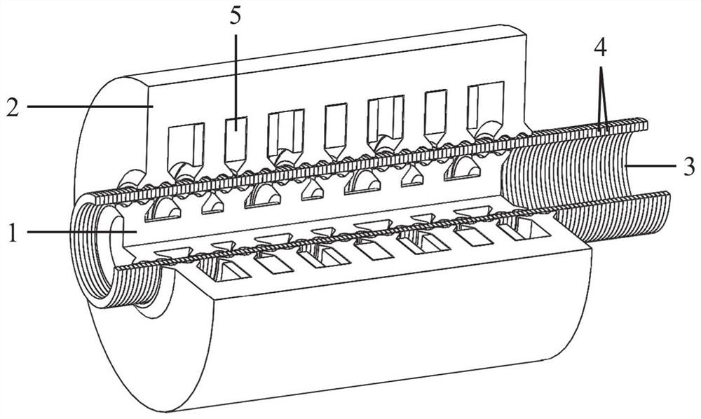
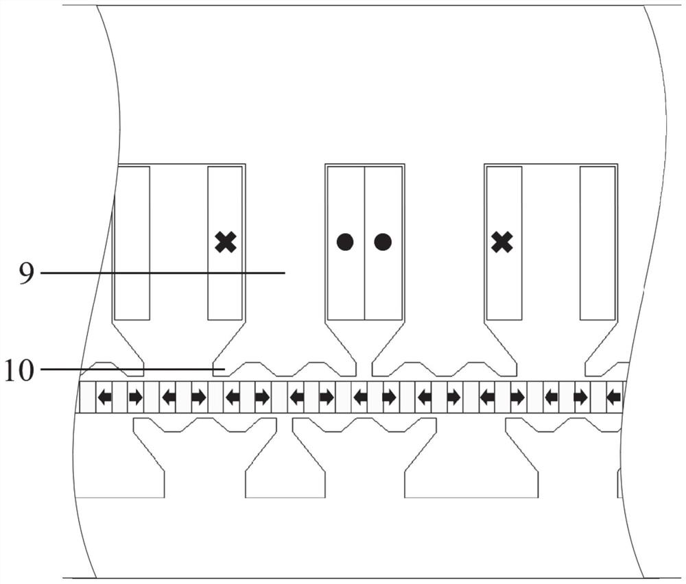
[0027] A double-stator split-tooth cylindrical linear motor, including a mover, an inner stator and an outer stator that face each other and are arranged on both sides of the mover. The mover is a magnet-condensing permanent magnet structure, and the permanent magnet is along The moving direction of the mover is magnetized horizontally, and the magnetization directions of the two adjacent permanent magnets are opposite;

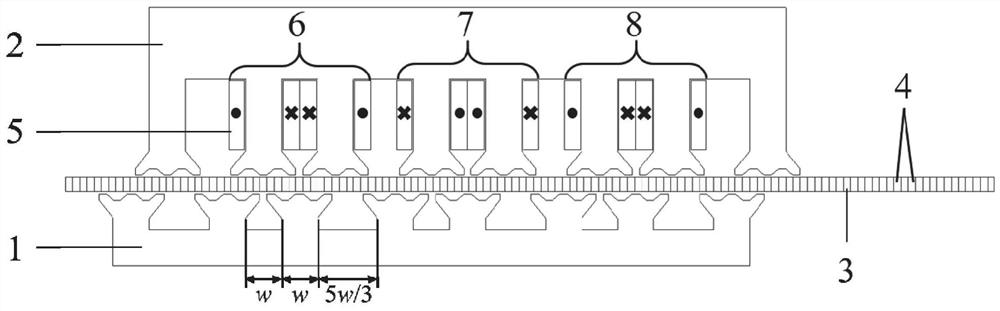
[0028] The main stator teeth of the inner stator and the outer stator are provided with several split teeth, the outer stator is provided with a phase group concentrated coil winding, the inner stator has no winding, and the two stators have a certain air gap distance from the mover respectively. The air gap distances are equal, and the two stators have an offset of the main stator tooth width along the moving direction of the mover.

[0029] Specifica...

Embodiment 2

[0040] The purpose of this embodiment is to provide a driving mechanism / power mechanism.

[0041] A driving mechanism / power mechanism, which adopts the above-mentioned double-stator split-tooth cylindrical linear motor, the linear motor includes: a mover and an inner stator and an outer stator facing each other and arranged on both sides of the mover. The mover is a magnet-concentrating permanent magnet structure, and the permanent magnet is magnetized horizontally along the moving direction of the mover, and the magnetization directions of two adjacent permanent magnets are opposite;

[0042] The main stator teeth of the inner stator and the outer stator are provided with several split teeth, the outer stator is provided with a phase group concentrated coil winding, the inner stator has no winding, and the two stators have a certain air gap distance from the mover respectively. The air gap distances are equal, and the two stators have an offset of the main stator tooth width ...


PUM


Abstract

The invention provides a double-stator split tooth type cylindrical linear motor. The double-stator split tooth type cylindrical linear motor comprises an inner stator, a rotor and an outer stator; the rotor is of a magnetism gathering type permanent magnet rotor structure, the permanent magnets are horizontally magnetized in the moving direction of the rotor, and the magnetization directions of every two adjacent permanent magnets are opposite; the outer stator is provided with a phase group concentrated winding, and the inner stator is not provided with a winding; the inner stator and the outer stator are both of a split tooth structure; and a certain air gap distance exists between each stator and the rotor, the two air gap distances are equal, and the two stators have the offset of the width of one main stator tooth in the moving direction of the rotor. According to the scheme, high power density and high output thrust are achieved, and magnetic resistance and thrust fluctuation are effectively restrained.

Description

technical field [0001] The disclosure belongs to the field of design and manufacture of linear motors, in particular to a double-stator split-tooth cylindrical linear motor. Background technique [0002] The statements in this section merely provide background information related to the present disclosure and do not necessarily constitute prior art. [0003] In the current industrial manufacturing field, the demand for intelligence and personalization is becoming increasingly urgent. Facing the ever-changing production requirements and increasingly complex manufacturing technologies, the flexible conveying system provides a solution for manufacturers, which effectively reduces the Production costs and improved production efficiency. Flexible conveying systems generally use linear motors. Compared with rotary motors, linear motors can directly achieve linear motion without the use of conversion mechanisms. They have the advantages of simple structure, small size, low cost, a...

Claims


Application Information

Patent Timeline
Patent Type & Authority Applications(China)
IPC IPC(8): H02K16/04H02K1/27H02K1/14
Inventor 赵文良许金阳王晓东王秀和
Owner SHANDONG UNIV
Why Eureka
Try Eureka