
Brush frame structure of cleaning robot

A technology of robots and brush racks, applied in animal houses, chemical instruments and methods, cleaning methods and utensils, etc. problems, to achieve the effect of enhancing adaptability and work ability

Pending Publication Date: 2020-05-22
哈尔滨天河自动化设备有限公司
View PDF0 Cites 0 Cited by
  • Summary
  • Abstract
  • Description
  • Claims
  • Application Information

AI Technical Summary

Problems solved by technology

[0002] At present, most of the animal husbandry developed in the background of modern agriculture relies on manual labor as a service support. A few large-scale animal husbandry places have introduced semi-automatic service equipment. For the cleaning of pig houses in large pig farms, it is still necessary Manually use tools to clean and consume a lot of water to clean up, which takes a long time, high cost and low efficiency
The existing intelligent cleaning robot equipment has few functions of the brush frame and a small cleaning range. Since it is arranged in the middle of the bottom of the vehicle, the wheels will first contact the feces during the cleaning process, which is easy to form feces accumulation, and it can only be used on pigs with leaking feces floors. Therefore, it is necessary to aim at the pig house cleaning work involved in this field, and develop a new type of pig house cleaning robot brush frame structure to improve the environmental conditions of the pig house

Method used


Image

  • Brush frame structure of cleaning robot
  • Brush frame structure of cleaning robot
  • Brush frame structure of cleaning robot

Examples


Embodiment Construction

[0033] It should be noted that, in the case of no conflict, the embodiments of the present invention and the features in the embodiments can be combined with each other.

[0034] The present invention will be described in detail below with reference to the accompanying drawings and examples.

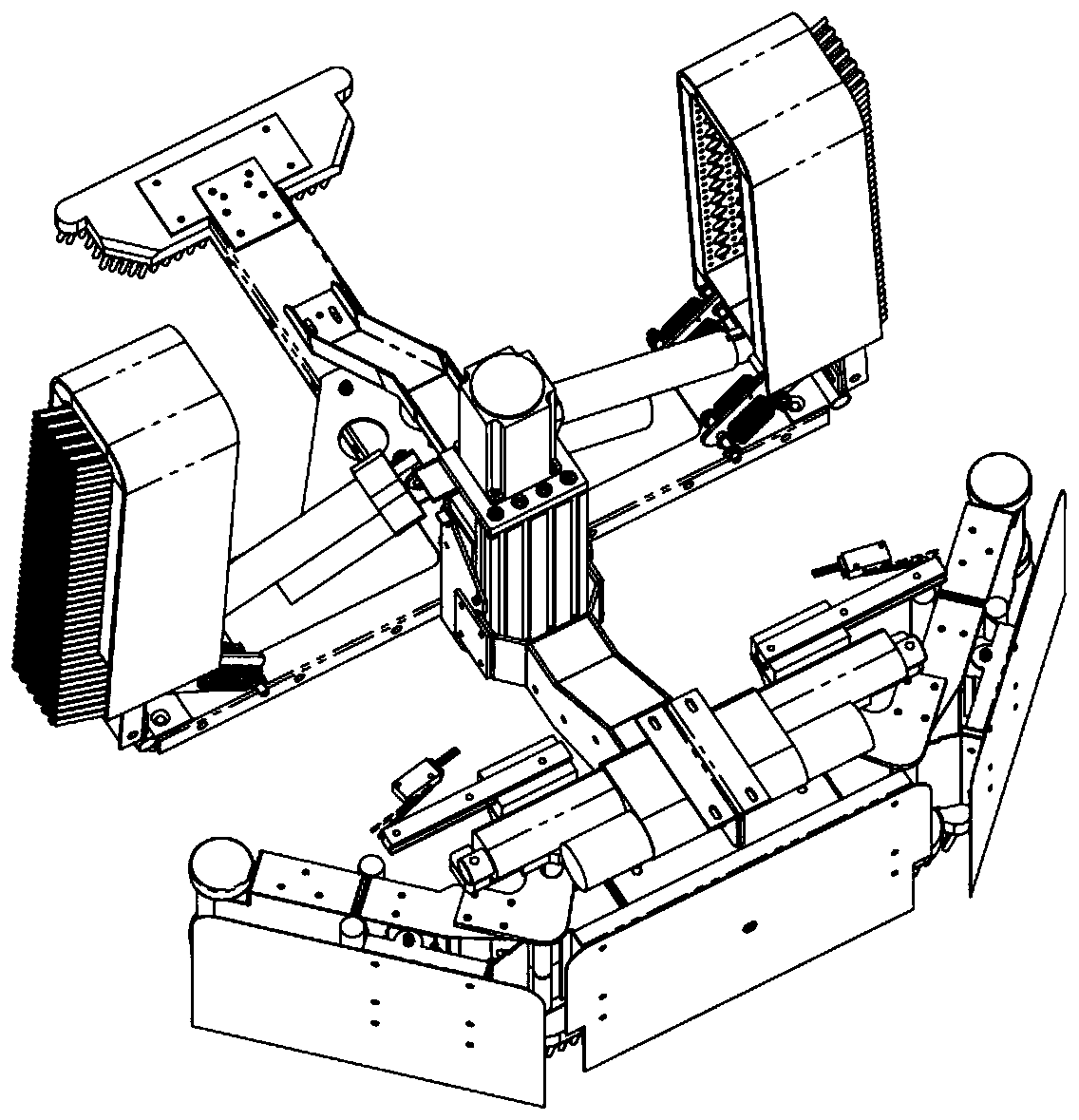
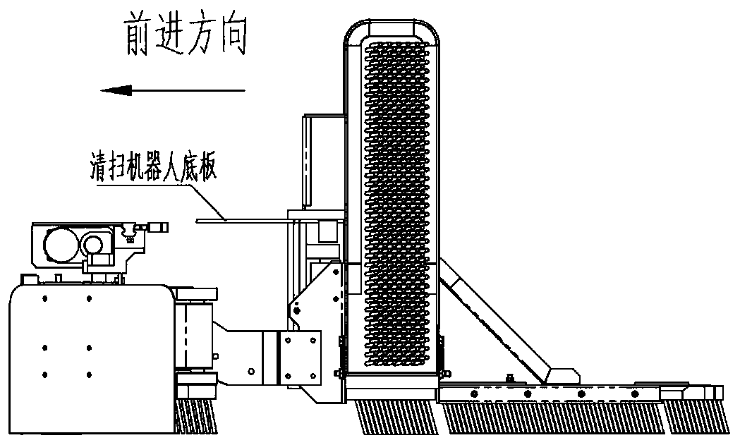
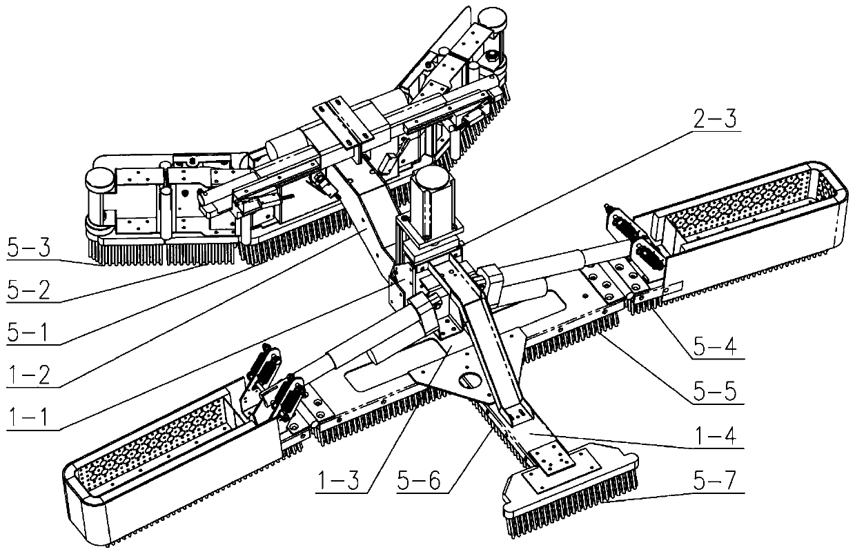
[0035] Such as Figure 1-Figure 6 As shown, a multifunctional cylinder liner automatic detection device includes a main brush holder, a lifting assembly, a front brush holder assembly and a side brush holder assembly; the main brush holder includes a brush holder vertical beam 1-1, a brush holder front connection Beam 1-2, brush frame middle beam 1-3 and tail brush groove 1-4, the lifting assembly drives the brush frame vertical beam 1-1 to move up and down, and the brush frame front connecting beam 1-2 is fixed on the brush frame vertical The front side of the beam 1-1, the brush holder intermediate beam 1-3 is fixed on the rear side of the brush holder vertical beam 1-1, and the tail ...


PUM


Abstract

The invention provides a brush frame structure of a cleaning robot. The brush frame structure comprises a main brush frame, a lifting assembly, a front brush frame assembly and a side brush frame assembly; the main brush frame comprises a brush frame vertical beam, a brush frame front connecting beam, a brush frame middle beam and a tail brush slot, the lifting assembly drives the brush frame vertical beam to move up and down, the brush frame front connecting beam is fixed at the front side of the brush frame vertical beam, the brush frame middle beam is fixed at the rear side of the brush frame vertical beam, and the tail brush slot is fixed at the rear side of the brush frame middle beam; and the front brush frame assembly comprises a front push plate, a front floating plate, a side brush push plate, a side brush floating plate and an electric push rod B, the side brush frame assembly comprises two side brush frames, two waist hole spring brackets and two electric push rods A, and the bottom of the front push plate, the bottom of the side brush push plate, the bottom of the brush frame middle beam, the bottom of the side brush frame and the tail brush slot are all matched with brushes. According to the present invention, cleaning on the side of the body is realized, the cleaning range and cleaning efficiency are improved, and the adaptability and cleaning ability of the cleaning robot to the ground environment are enhanced.

Description

technical field [0001] The invention belongs to the technical field of agricultural intelligent equipment, and in particular relates to a brush holder structure of a cleaning robot. Background technique [0002] At present, most of the animal husbandry developed in the background of modern agriculture relies on manual labor as a service support. A few large-scale animal husbandry places have introduced semi-automatic service equipment. For the cleaning of pig houses in large pig farms, it is still necessary Manual use of tools to clean and consume a large amount of water can be cleaned up, which takes a long time, high cost and low efficiency. The existing intelligent cleaning robot equipment has few functions of the brush frame and a small cleaning range. Since it is arranged in the middle of the bottom of the vehicle, the wheels will first contact the feces during the cleaning process, which is easy to form feces accumulation, and it can only be used on pigs with leaking f...

Claims


Application Information

Patent Timeline
Patent Type & Authority Applications(China)
IPC IPC(8): A01K1/01B08B1/00
CPCA01K1/0132A01K1/0128B08B1/12
Inventor 路卫国赵庆江张万录
Owner 哈尔滨天河自动化设备有限公司
Features
  • Generate Ideas
  • Intellectual Property
  • Life Sciences
  • Materials
  • Tech Scout
  • Unparalleled Data Quality
  • Higher Quality Content
  • 60% Fewer Hallucinations
Learn More