
Locking device and luggage case with same

A locking device and locking technology, applied to luggage, travel goods, clothing, etc., can solve the problems of inconvenient storage of luggage, occupying space, and low frequency of use of luggage and luggage, so as to ensure reliability, The effect of convenient size adjustment and convenient operation

Pending Publication Date: 2020-05-22
张效益 +1
View PDF1 Cites 3 Cited by
  • Summary
  • Abstract
  • Description
  • Claims
  • Application Information

AI Technical Summary

Problems solved by technology

For the former, the size of the use space inside the box is fixed, and the storage space inside the box cannot be changed according to actual needs, and the frequency of use of the box (especially the suitcase) is low, and most of the time it is in an idle state. For large and small boxes, it will take up a certain amount of storage space, which is not convenient for the storage of boxes
[0003] For the latter, it can change the storage space inside the box according to the actual storage needs, so that the practicability of the box is better, but for the current variable volume box, it is mainly in the original box. On the basis of adding a detachable box, the two are connected together through a locking structure. For example, in the application with the authorization announcement number CN208114187U and the name "A Luggage Box with Adjustable Size", it is locked by a zipper. The locking structure is used to realize the connection between the movable box, the top box, and the bottom box. This method is not convenient and labor-saving in actual use.

Method used


Image

  • Locking device and luggage case with same
  • Locking device and luggage case with same
  • Locking device and luggage case with same

Examples


Embodiment 1

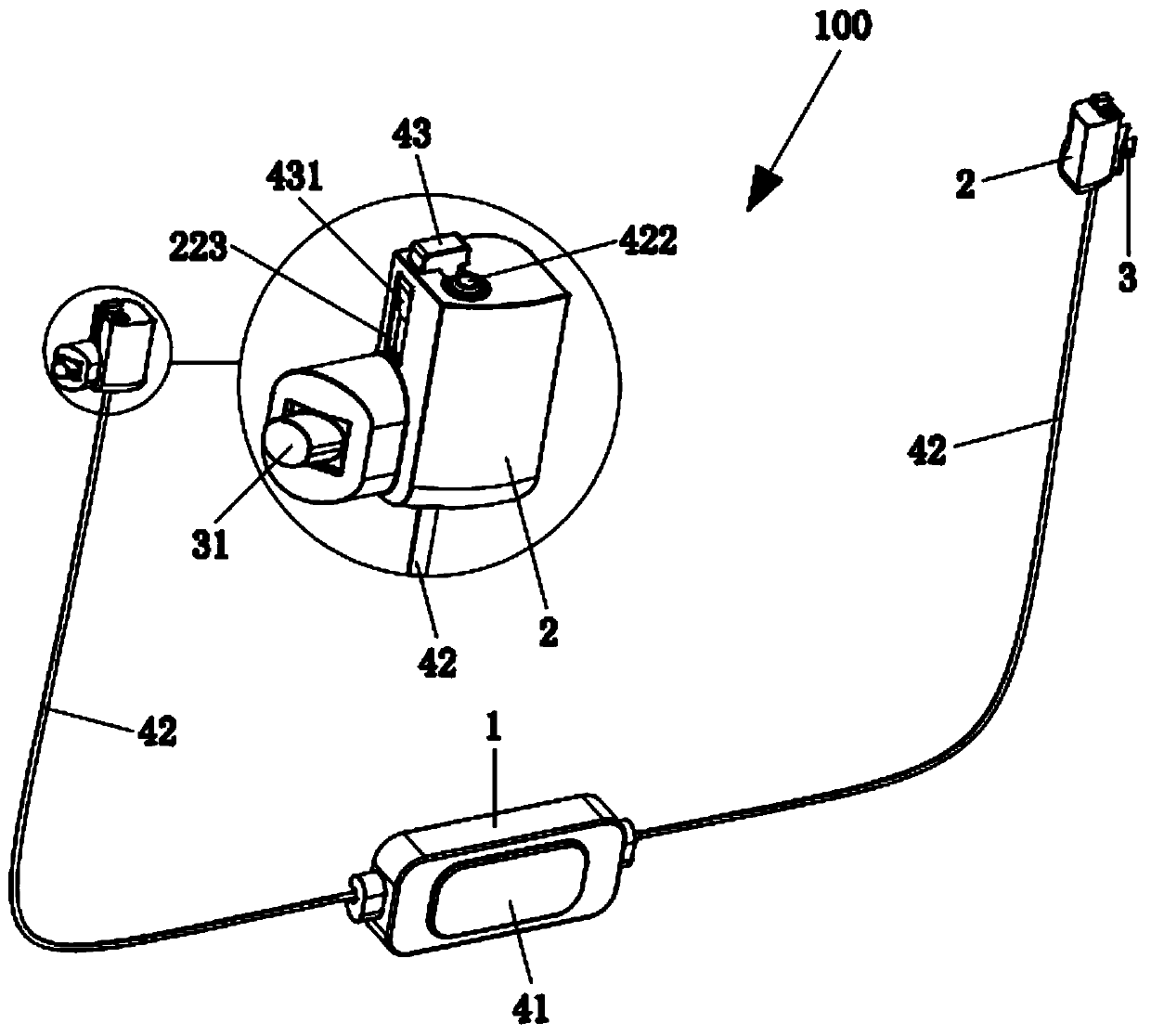
[0039] refer to figure 1 As shown, the present invention discloses a locking device 100, which includes a hollow housing 1, a locking seat 2, a locking mechanism 3 and a linkage mechanism.

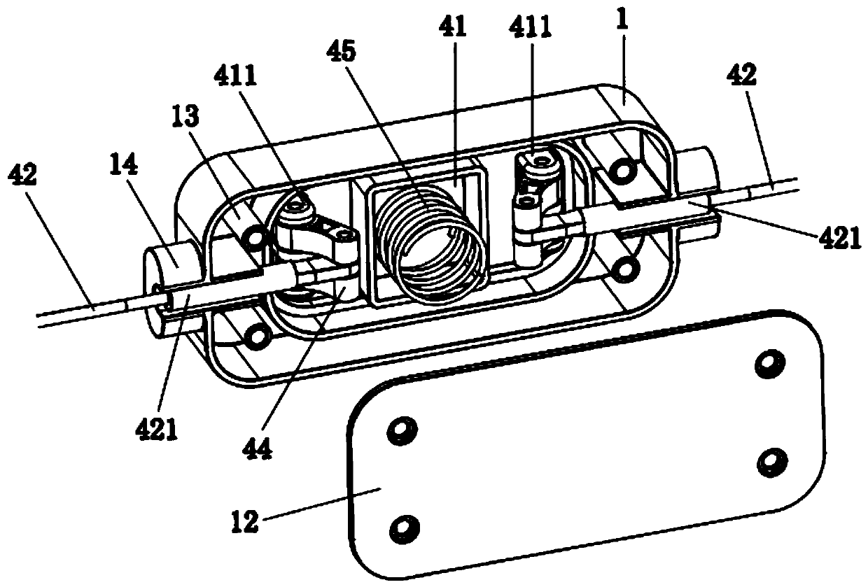
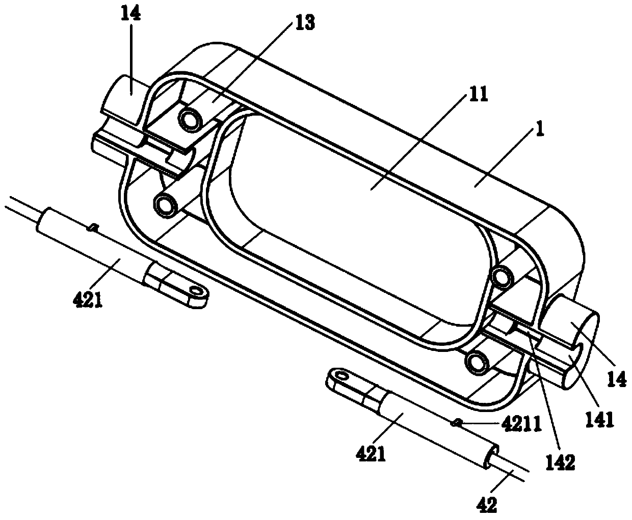
[0040] Cooperate Figure 1 to Figure 3 As shown, the front side of the housing 1 is provided with an installation port 11 for installing the button 41, and the rear side of the housing 1 is provided with a housing cover 12 for closing it. The housing 1 is provided with several columns 13, and the housing cover 12 is fixed. On the column 13 , an extension portion 14 is formed on the side of the housing 1 . The extension portion 14 is provided with a groove 141 communicating with the inside of the housing 1 . The groove 141 is provided with a positioning groove 142 along its length.

[0041] Cooperate figure 1 , Figure 4 and Figure 5 As shown, the locking seat 2 is provided with an accommodating cavity 21, the locking seat 2 includes a first seat body 22 and a second seat body 23, the ...

Embodiment 2

[0049] Cooperate figure 1 , Image 6 and Figure 7 As shown, the difference between this embodiment and Embodiment 1 is:

[0050] The first seat body 22 extends to the side to form several second seat bodies 23, the first seat body 22 is provided with the installation groove 221 corresponding to the number of the second seat body 23, each second seat body 22 is provided with There are accommodating cavities 21, which respectively communicate with the mounting grooves 221, and the accommodating cavities 21 are provided with lock pins 31 and first springs 32, and the number of thrust members 43 corresponds to the number of the first seat 22 , and the connecting portions 432 of the thrust pieces 43 are connected together, and the thrust pieces 43 abut against the thrust openings 3111 of the locking pins 31 respectively.

[0051] In this embodiment, the number of the second seat 23 formed by extending the first seat 22 to the side is preferably two, and the number of thrust pie...

Embodiment 3

[0053] Cooperate figure 1 , Figure 8 to Figure 12 As shown, the present invention also discloses a suitcase, comprising a lower box 200, an upper box 300 and the above-mentioned locking device 100, the lower box 200 is provided with a lower lock hole 210, and the upper box 300 is connected with the lower box There are at least two upper lock holes 310 on the same plane as the lock holes 210. The lock device 100 is arranged on the inner side wall of the lower box body 200, and the lock pin 31 of the lock device 100 extends into the lower lock hole 210. and inserted into one of the upper locking holes 310 to connect the lower case body 200 and the upper case body 300 together.

[0054] In this embodiment, a slide rail 220 is provided on the lower box body 200, and the slide rail 220 is arranged along the height direction of the lower box body 200; When the upper box 300 moves relative to the lower box 200, the matching between the slider 320 and the slide rail 220 can not onl...


PUM


Abstract

The invention discloses a locking device. The locking device comprises a shell, a locking seat, a locking mechanism and a linkage mechanism, an accommodating cavity is formed on the locking seat, andthe locking mechanism comprises a lock pin and a first spring. The lock pin is arranged in the accommodating cavity, the first spring abuts against the lock pin, and the linkage mechanism comprises abutton, a pull rope and a thrust piece. The button is arranged on the shell, the lower end of the pull rope is connected with the button, the upper end of the pull rope is connected with the thrust piece, and one end of the lock pin retracts into / stretches out of the accommodating cavity through the thrust piece. The present invention further discloses a luggage case which comprises a lower case body, an upper case body and the locking device. A lower lock hole is formed on the lower case body, at least two upper lock holes are formed on the upper case body, and the lock pin extends into the lower lock hole and is inserted into one upper lock hole so as to connect the lower case body and the upper case body together. The locking device is very convenient and labor-saving to operate, and the luggage case disclosed by the invention not only can meet different requirements for use and placement, but also is very convenient to adjust the size.

Description

technical field [0001] The invention relates to the technical field of daily necessities, in particular to a locking device and a luggage case with the locking device. Background technique [0002] In the field of boxes, it is divided into two types: fixed volume and variable volume. For the former, the size of the use space inside the box is fixed, and the storage space inside the box cannot be changed according to actual needs, and the frequency of use of the box (especially the suitcase) is low, and most of the time it is in an idle state. In terms of large and small cases, it will take up a certain amount of storage space, which is not convenient for the storage of the case. [0003] For the latter, it can change the storage space inside the box according to the actual storage needs, so that the practicability of the box is better, but for the current variable volume box, it is mainly in the original box. On the basis of adding a detachable box, the two are connected t...

Claims


Application Information

Patent Timeline
Patent Type & Authority Applications(China)
IPC IPC(8): A45C7/00A45C13/00
CPCA45C7/0031A45C13/001
Inventor 张效益金星攀
Owner 张效益
Learn More