
Maglev centrifugal compressor and its control method

A technology of centrifugal compressor and control method, which is applied in the direction of compressor, irreversible cycle compressor, pump control, etc. It can solve the problem of inability to adjust the gas leakage and control the size of the axial force, and the inability to adjust the clearance of the labyrinth shaft seal And other issues

Active Publication Date: 2021-08-06
IND TECH RES INST
View PDF10 Cites 0 Cited by
  • Summary
  • Abstract
  • Description
  • Claims
  • Application Information

AI Technical Summary

Problems solved by technology

It can be seen that since the gap of the labyrinth shaft seal cannot be adjusted, the gas leakage and the axial force cannot be adjusted.

Method used


Image

  • Maglev centrifugal compressor and its control method
  • Maglev centrifugal compressor and its control method
  • Maglev centrifugal compressor and its control method

Examples


Embodiment Construction

[0076]The specific implementation manners of the present invention will be further described below in conjunction with the accompanying drawings and examples. The following examples are only used to illustrate the technical solutions of the present invention more clearly, but not to limit the protection scope of the present invention. It should be noted that, in the descriptions of the various embodiments, the descriptions of "upper / upper", "lower / lower", "front end / front" or "rear end / rear", "left" or "right" etc. This formula is described as a baseline, but other possible changes in direction are also included. In addition, the so-called "first", "second", "third", and "fourth" are used to describe various elements, and these elements are not limited by such terms. For the convenience and clarity of illustration, the thickness or size of each element in the drawings is exaggerated or omitted or shown in a rough manner, and the size of each element is not entirely its actual...


PUM


Abstract

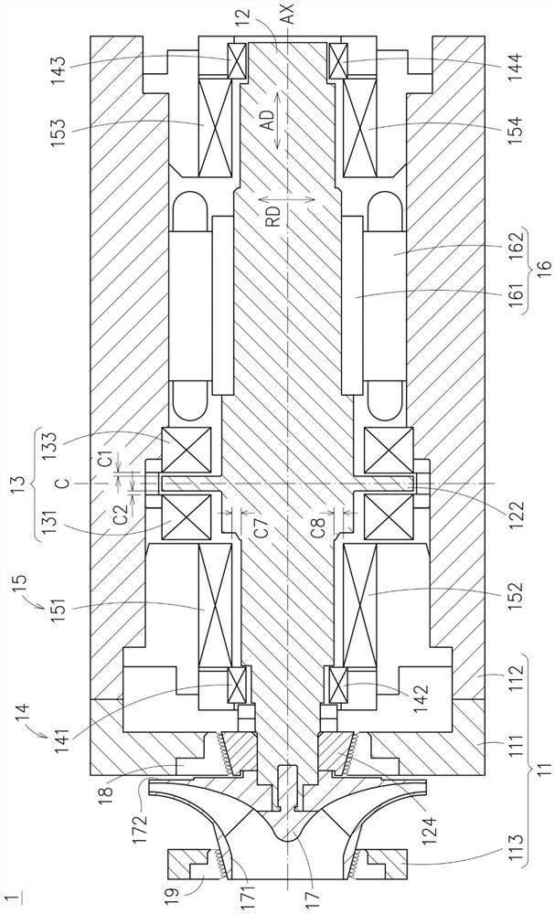
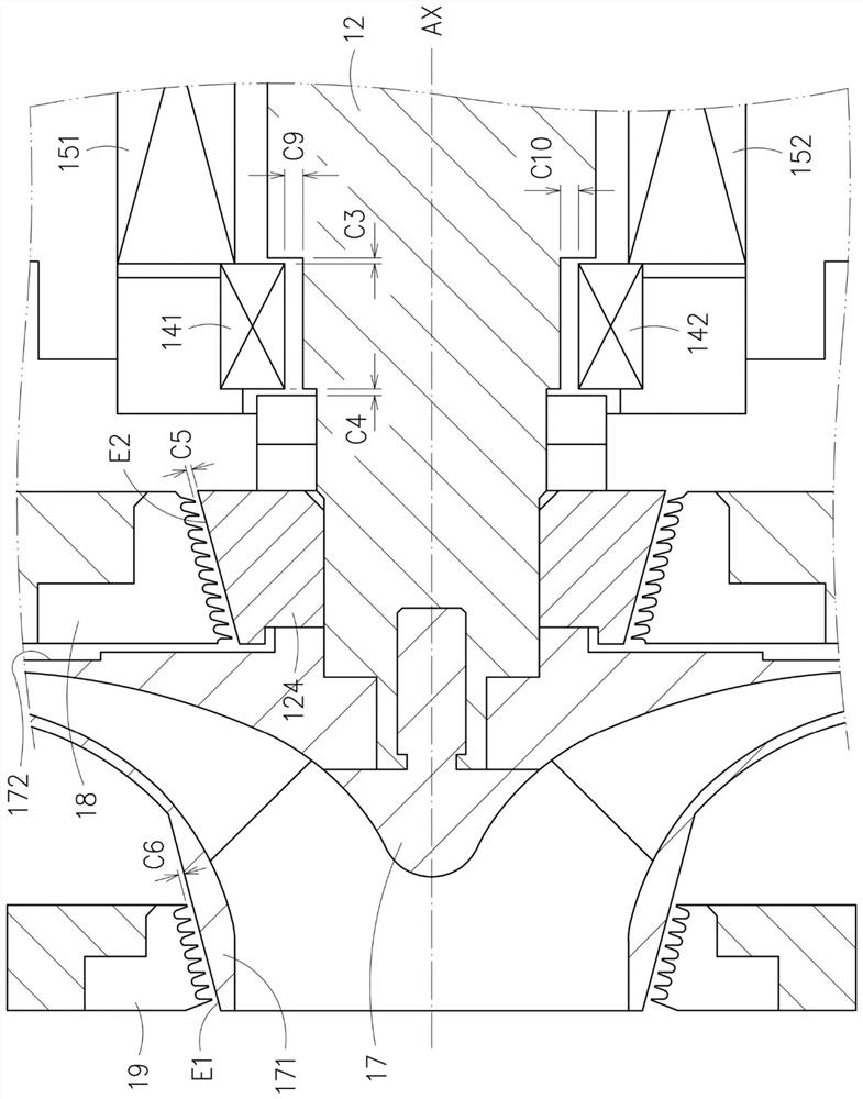
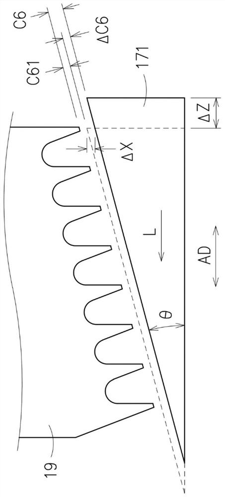
A maglev centrifugal compressor includes a maglev main shaft, a thrust disc, a front axial bearing and a rear axial bearing, an impeller and at least one labyrinth shaft seal. The thrust disc is connected to the maglev main shaft. There is a first clearance between the rear axial bearing and the thrust disc, and there is a second clearance between the front axial bearing and the thrust disc. The impeller is connected to the maglev main shaft. The labyrinth seal is arranged obliquely relative to the axial direction of the maglev main shaft, and there is a labyrinth seal gap between the labyrinth seal and the maglev main shaft and / or the impeller. By controlling the position of the thrust disc in the axial direction, the first The gap ratio of the first gap to the second gap is used to adjust the gap of the labyrinth shaft seal. In addition, a control method for a maglev centrifugal compressor is also proposed.

Description

technical field [0001] The invention relates to a magnetic suspension centrifugal compressor and a control method thereof. Background technique [0002] The centrifugal compressor works on the gas for the impeller to increase the pressure and speed of the gas, complete the transportation of the gas, and make the gas flow through the compressor of the impeller. When the impeller rotates at high speed, the gas rotates with it. Under the action of centrifugal force, the gas is thrown into the diffuser behind, and a vacuum zone is formed at the impeller. At this time, the fresh gas from the outside enters the impeller. The impeller rotates continuously, and the gas is continuously sucked in and thrown out, thus maintaining a continuous flow of gas. [0003] In recent years, in order to achieve high-speed rotation, the main shaft of the centrifugal compressor is rotatably supported by a magnetic bearing. The main shaft and the bearing are not in contact without frictional heat,...

Claims


Application Information

Patent Timeline
Patent Type & Authority Patents(China)
IPC IPC(8): F04D17/10F04D27/00F04D29/053F04D29/056F04D29/10
CPCF04D17/10F04D27/00F04D29/053F04D29/056F04D29/102F04D29/051F04D29/0516F04D29/052F04D29/058F04D29/10F05D2240/51F25B1/04
Inventor 林俊傑鐘震麒刘中哲洪国书
Owner IND TECH RES INST
Learn More