Lamp heat dissipation structure and ceiling lamp

A technology of heat dissipation structure and lamps, applied in lighting and heating equipment, cooling/heating devices of lighting devices, lighting devices, etc., can solve the problems of low assembly efficiency and complex heat dissipation fin process, so as to improve assembly efficiency and reduce production The effect of simple cost and connection structure

Pending Publication Date: 2020-05-22
LEEDARSON IOT TECH INC
View PDF0 Cites 1 Cited by
  • Summary
  • Abstract
  • Description
  • Claims
  • Application Information

AI Technical Summary

Problems solved by technology

[0003] The purpose of the present invention is to provide a heat dissipation structure of a lamp and a high-ceiling lamp, so as to solve the technical problems in the prior art that the process of assembling heat dissipation fins by riveting is complicated and the assembly efficiency is low

Method used


Image

  • Lamp heat dissipation structure and ceiling lamp
  • Lamp heat dissipation structure and ceiling lamp
  • Lamp heat dissipation structure and ceiling lamp

Examples


specific Embodiment approach

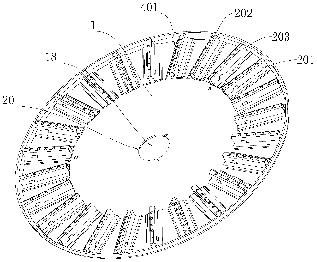
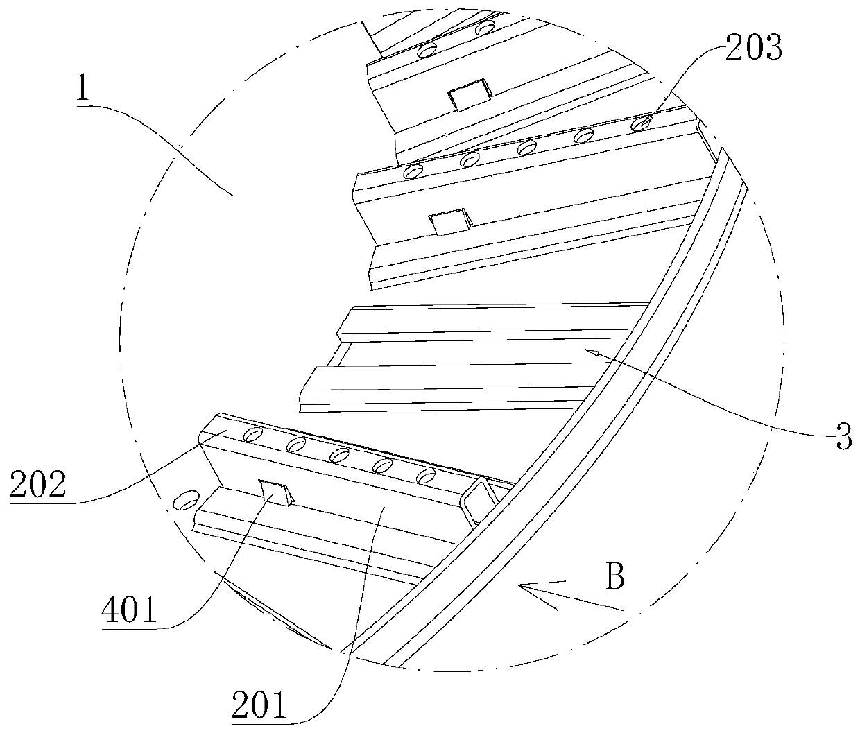
[0049] Please also refer to Figure 1 to Figure 7 , as a specific implementation of the heat dissipation structure of the lamp provided by the present invention, the buckle member 4 includes a buckle 401 and a limiting plate 402. There are multiple buckles 401, and the multiple buckles 401 are respectively located on the sides of the heat dissipation fins 2. On both sides, the limiting plate 402 is arranged at the front end of the cooling fin 2 , and the buckle 401 and the limiting plate 402 are used to clamp the rear shell 1 from the front and rear sides of the bayonet 3 .

[0050] The cooling fins 2 are gradually inserted backward into the bayonet socket 3 from the front side of the rear shell 1, and the cooling fins 2 gradually protrude backward from the bayonet socket 3. During the insertion process, the buckle 401 is compressed and gradually shrinks, so that the cooling fins 2 can Continue to push backward, when inserted in place, the limit plate 402 abuts against the fro...

Embodiment approach

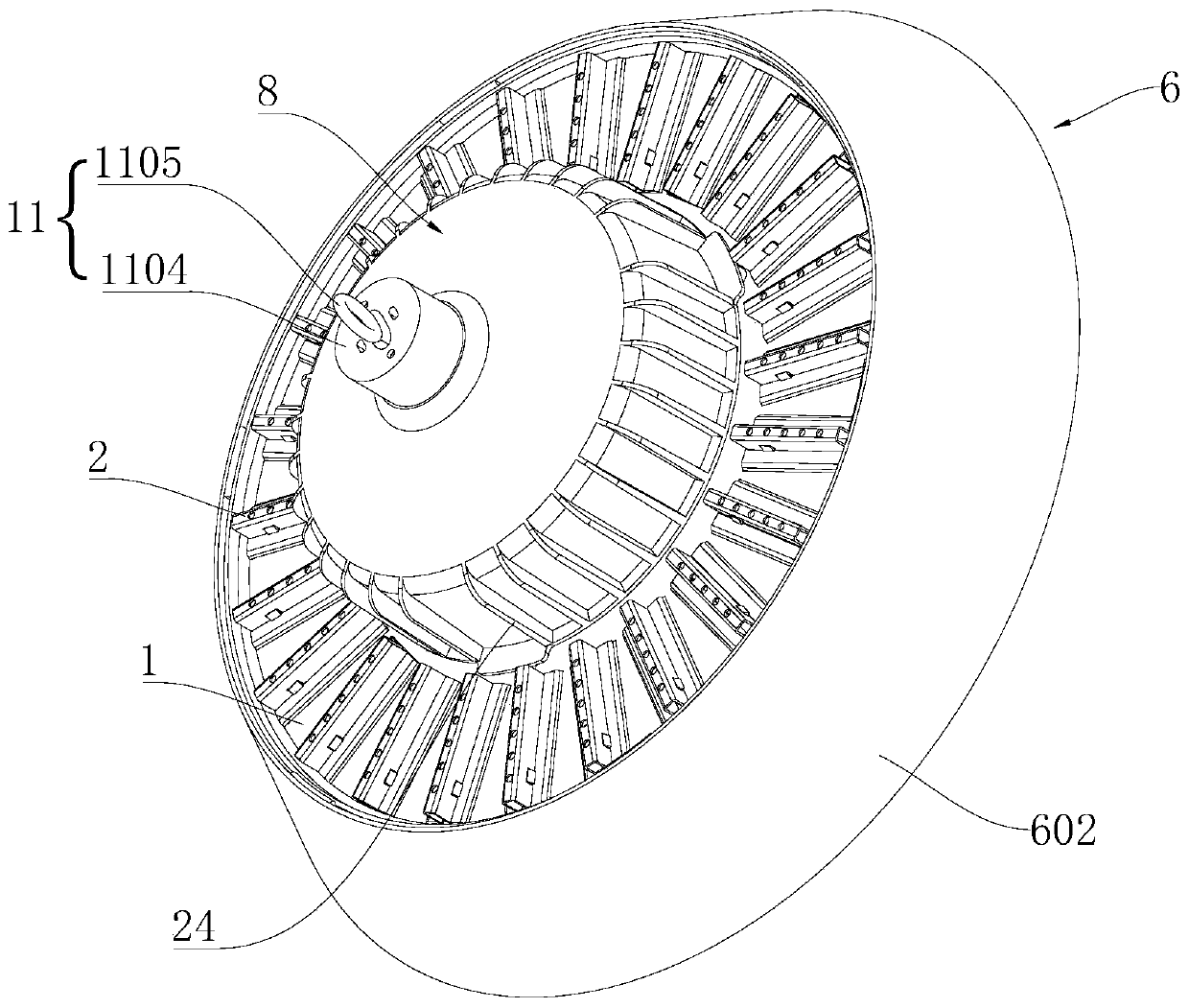
[0078] see figure 1 , Figure 7 , Figure 14 and Figure 15 , as a specific embodiment of the high dome lamp provided by the present invention, the lampshade 6 includes a front cover body 601 and a side cover body 602 arranged on the outer periphery of the front cover body 601, and the side cover body 602 protrudes forward from the front cover body 601 The front end face is integrally arranged with the front cover body 601 , the aforementioned second buckle 17 is arranged in the middle of the front cover body 601 , and the inner diameter of the side cover body 602 gradually decreases from front to back. The lampshade 6 forms a turn-around structure, which not only emits light downwards, but also diffuses light upwards, which can slightly illuminate the ceiling and provide different lighting effects. The integrated structure of the front cover body 601 and the side cover body 602 enables the lampshade 6 to be manufactured through a set of moulds, which simplifies the manufac...


PUM


Abstract

The invention provides a lamp heat dissipation structure and a ceiling lamp, and belongs to the field of lighting equipment. The lamp heat dissipation structure comprises a rear shell and heat dissipation fins, the rear shell is provided with bayonets, the heat dissipation fins penetrate through the bayonets, and the heat dissipation fins are provided with buckle components used for being connected with the bayonets in a clamped mode. According to the lamp heat dissipation structure and the ceiling lamp, the heat dissipation fins can penetrate through the bayonets, pre-positioning in the clamping process is achieved, finally clamping with the bayonets is achieved through the buckle components, riveting through riveting pieces is not needed, the connecting structure is simple, the assembling process is simple, and the assembling efficiency can be improved to a large extent.

Description

technical field [0001] The invention belongs to the technical field of lighting equipment, and more specifically relates to a heat dissipation structure of a lamp and a high dome lamp including the heat dissipation structure of the lamp. Background technique [0002] High ceiling lights are often used for lighting in places with high ceiling heights, such as sports venues, metallurgical workshops, power plants, industrial and mining plants, etc. The lighting components generate a lot of heat during the working process, and need to dissipate heat in time. The existing heat dissipation structure generally makes the light source board contact with the back shell for heat conduction, and then uses the cooling fins on the back shell to conduct heat with the air. The exchange completes the final heat dissipation. However, the heat dissipation fins are generally fixed on the rear shell by riveting, and the assembly process is complicated, which is not conducive to improving assembl...

Claims


Application Information

Patent Timeline
Patent Type & Authority Applications(China)
IPC IPC(8): F21V29/77F21V29/83F21V17/16F21V17/10
CPCF21V17/10F21V17/164F21V29/77F21V29/83
Inventor 曹亮亮许金
Owner LEEDARSON IOT TECH INC
Why Eureka
Try Eureka