Supercharge Your Innovation With Domain-Expert AI Agents!

Relative humidity sensor device

A sensor device, relative humidity technology, applied in measurement devices, instruments, scientific instruments, etc., can solve the problems of high driving current, large space, expensive and so on

Inactive Publication Date: 2020-05-22
梅斯法国公司
View PDF0 Cites 3 Cited by
  • Summary
  • Abstract
  • Description
  • Claims
  • Application Information

AI Technical Summary

Problems solved by technology

However, today's trim circuits require relatively large space on printed circuit boards, are relatively expensive, and require relatively high drive currents

Method used


Image

  • Relative humidity sensor device
  • Relative humidity sensor device
  • Relative humidity sensor device

Examples


Embodiment Construction

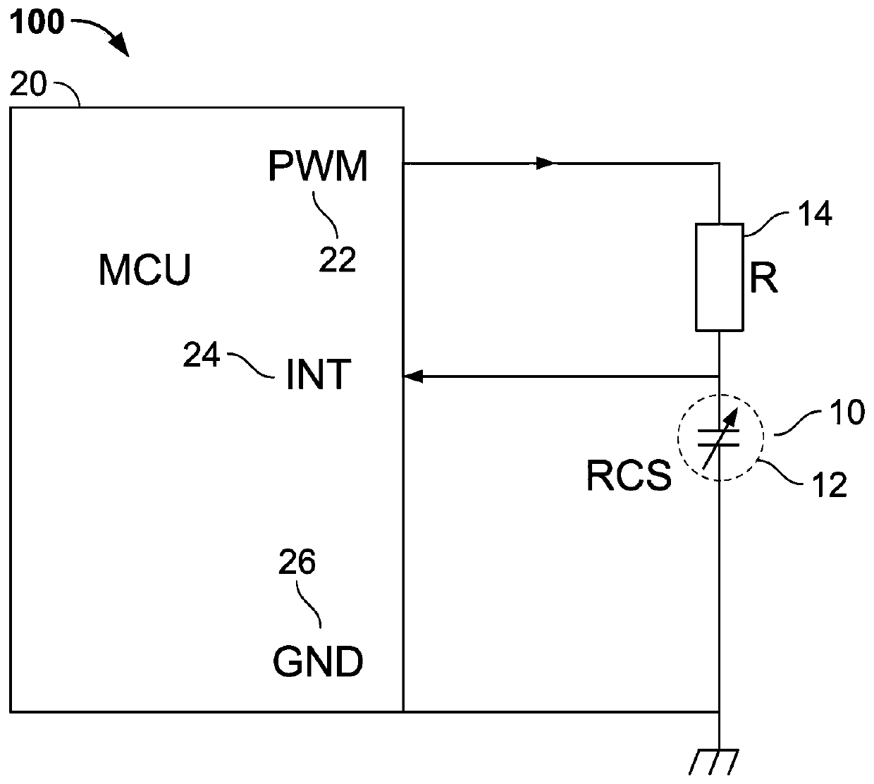
[0047] The present invention provides a relative humidity sensor comprising a microcontroller and a capacitive sensor element. This humidity sensor determines the relative humidity and dew point in the environment. figure 1 Portions of an embodiment of a humidity sensor 100 are shown. The humidity sensor 100 comprises a sensor element 10 comprising a sensing capacitor 12 . A sensing capacitor 12 is connected in series to a resistor 14 . Resistor 14 may be several hundred kilohms, for example 470 kilohms.

[0048] The sensing capacitor 12 has a variable capacitance depending on the humidity of the ambient conditions. For example, the sensing capacitor 12 includes a pair of electrodes each covered with a silicon nitride film and a moisture sensitive film. A moisture sensitive film is provided between the electrodes and may also cover the electrodes (formed over the silicon nitride film). The capacitance between the electrodes can vary depending on the humidity of the air ar...


PUM

PropertyMeasurementUnit
capacitanceaaaaaaaaaa

Abstract

The present invention relates to a relative humidity sensor device, comprising a microcontroller and a sensing capacitor connected to a resistor. The microcontroller comprises a pulse width modulatorwith an output connected via the resistor to the sensing capacitor and an interrupt input connected to the sensing capacitor and a counter. Further, the microcontroller is configured to periodically charge and discharge the sensing capacitor via the resistor by means of the pulse width modulator, determine a number of interrupt events by means of the counter and determine a charging time of the sensing capacitor based on the determined number of interrupt events.

Description

technical field [0001] The present invention relates to a relative humidity sensor device, and in particular to means for acquiring data from a sensor element of the relative humidity sensor device. Background technique [0002] Humidity can be measured by a variety of techniques based on changes in resistance and changes in capacitance of suitable materials. In semiconductor-based systems for determining relative humidity (the ratio of the partial pressure of water vapor to the saturated vapor pressure of water at a given temperature) by means of the measurement of capacitance, it is possible, for example, to base the reversible Water absorption properties to measure humidity. [0003] In general, a conventional capacitive relative humidity sensor device includes a semiconductor substrate, and a pair of electrodes formed on the surface of the semiconductor substrate and facing each other across a certain distance. A moisture sensitive dielectric film is placed between the...

Claims


Application Information

Patent Timeline
Patent Type & Authority Applications(China)
IPC IPC(8): G01N27/22
CPCG01N27/223G01N27/227G01N27/228G01N27/121H03K7/08
Inventor D.贝兹
Owner 梅斯法国公司
Features
  • R&D
  • Intellectual Property
  • Life Sciences
  • Materials
  • Tech Scout
  • Unparalleled Data Quality
  • Higher Quality Content
  • 60% Fewer Hallucinations
Learn More