Optical lens and imaging device
An optical lens and lens technology, applied in the field of optical lenses, can solve the problems of complex lens structure, difficult to eliminate the influence of ghost images, low product yield, etc., and achieve the effects of high imaging quality, improved camera experience, and high-definition imaging effects.
- Summary
- Abstract
- Description
- Claims
- Application Information
AI Technical Summary
Problems solved by technology
Method used
Image

Examples
no. 1 example
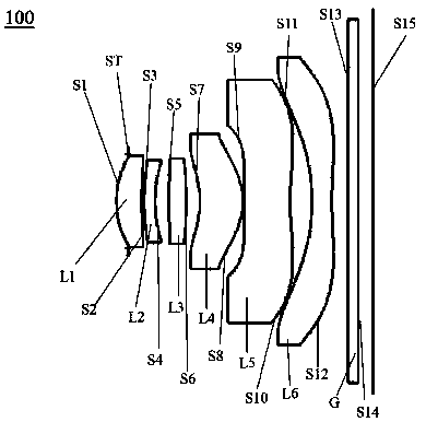
[0083] Please refer to figure 2 , which is a schematic structural view of the optical lens 100 provided by the first embodiment of the present invention, the optical lens 100 includes a stop ST, a first lens L1, a second lens L2, a third lens Lens L3, fourth lens L4, fifth lens L5 and sixth lens L6, and filter G.
[0084] The first lens L1 has positive refractive power, the object side S1 of the first lens is a convex surface, and the image side S2 of the first lens is a concave surface;
[0085] The second lens L2 has a negative refractive power, and the image side S4 of the second lens is concave;
[0086] The third lens L3 has a positive refractive power, and both the object side S5 of the third lens and the image side S6 of the third lens are convex and have no inflection points;
[0087] The fourth lens L4 has positive refractive power, the object side S7 of the fourth lens is concave, and the image side S8 of the fourth lens is convex at the near optical axis;
[008...
no. 2 example
[0099] Such as Image 6 As shown, it is a schematic structural diagram of the optical lens 200 provided by this embodiment. The optical lens 200 of this embodiment is substantially the same as that of the above-mentioned first embodiment, and the difference mainly lies in different design parameters.
[0100] Specifically, the design parameters of the optical lens 200 provided in this embodiment are shown in Table 3:
[0101] table 3
[0102]
[0103] In this embodiment, the aspheric parameters of each lens in the optical lens 200 are shown in Table 4.
[0104] Table 4
[0105]
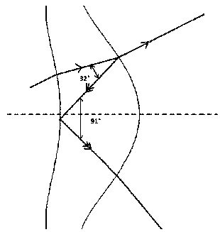
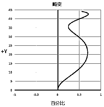
[0106] Please refer to Figure 7 , Figure 8 and Figure 9 , which are respectively the distortion curve diagram of the optical lens 200, the vertical axis chromatic aberration diagram, and the internal reflection ghost image optical path diagram of the fourth lens L4, from Figure 7 It can be seen that the optical distortion is controlled within 0.75%, indicating that the distortion of th...
no. 3 example
[0108] Such as Figure 10 As shown, it is a schematic diagram of the structure of the optical lens 300 provided in this embodiment. The optical lens 300 of this embodiment is roughly the same as the above-mentioned first embodiment, and the main difference lies in: the curved surface shapes of the fourth lens L4 and the fifth lens L5 There is a difference, the object side surface S7 of the fourth lens is smoother, which is beneficial to reduce the energy of the internal reflection ghost image of the fourth lens L4. The object side surface S9 of the fifth lens has a large edge recursion, that is, a large variation range of the edge curvature, which is beneficial for aberration correction.
[0109] Specifically, the design parameters of the optical lens 300 provided in this embodiment are shown in Table 5:
[0110] table 5
[0111]
[0112] In this embodiment, the aspheric parameters of each lens in the optical lens 300 are shown in Table 6.
[0113] Table 6
[0114]
...
PUM
 Abstract
Description
Claims
Application Information
 - R&D
- Intellectual Property
- Life Sciences
- Materials
- Tech Scout
- Unparalleled Data Quality
- Higher Quality Content
- 60% Fewer Hallucinations
Browse by: Latest US Patents, China's latest patents, Technical Efficacy Thesaurus, Application Domain, Technology Topic, Popular Technical Reports.
© 2025 PatSnap. All rights reserved.Legal|Privacy policy|Modern Slavery Act Transparency Statement|Sitemap|About US| Contact US: help@patsnap.com