An optical imaging lens

An optical imaging lens and lens group technology, applied in the field of optical lenses, can solve the problem that smartphones do not have telephoto lens components, and achieve the effect of improving camera experience and good applicability

Active Publication Date: 2020-11-17
JIANGXI LIANYI OPTICS CO LTD
View PDF6 Cites 0 Cited by
  • Summary
  • Abstract
  • Description
  • Claims
  • Application Information

AI Technical Summary

Problems solved by technology

In recent years, with the advancement of smart phone design and manufacturing technology, the telephoto system has been widely sought after by flagship mobile phones. However, telephoto lenses generally have more components, and under the trend of thinner and lighter bodies, smart phones do not have Sufficient depth to accommodate components of a telephoto lens

Method used


Image

  • An optical imaging lens
  • An optical imaging lens
  • An optical imaging lens

Examples


Embodiment 1

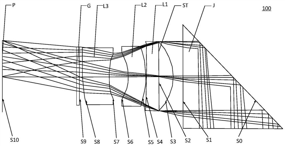
[0075] see figure 1 , is a structural diagram of the optical imaging lens 100 provided in the first embodiment of the present application, and relevant parameters of the optical imaging lens are shown in Table 1-1.

[0076] Table 1-1

[0077]

[0078]

[0079]The coordinate breakpoint in Table 1-1 is an imaginary plane, which is mainly used to indicate that all components and surfaces behind the imaginary plane are eccentric or deflected. In this embodiment, the aspherical parameters of each lens in the optical imaging lens 100 are shown in Table 1-2:

[0080] Table 1-2

[0081]

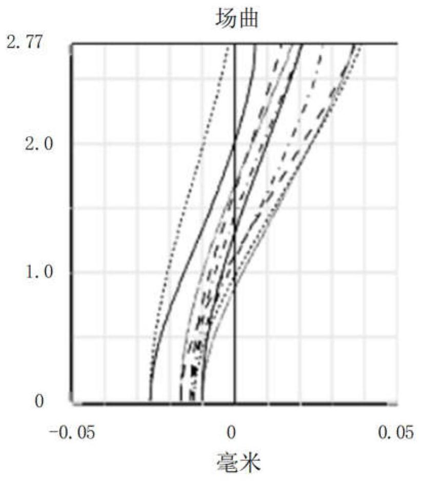
[0082] In this embodiment, the field curvature curve and distortion curve of the optical imaging lens 100 (f in the f-θ distortion in the figure is a percentage, and θ is an angle of view), the on-axis point spherical aberration curve, and the lateral chromatic aberration curve Figure respectively as image 3 , Figure 4 , Figure 5 and Figure 6 shown. From Figure 3 to Figure 6 It...

Embodiment 2

[0084] The structural diagram of the optical imaging lens 100 provided in this embodiment is substantially the same as that of the above-mentioned first embodiment, and the biggest difference lies in different design parameters. Specifically, the design parameters of the optical imaging lens 100 provided in this embodiment are shown in Table 2-1:

[0085] table 2-1

[0086]

[0087] In this embodiment, the aspherical parameters of each lens in the optical imaging lens 100 are shown in Table 2-2:

[0088] Table 2-2

[0089]

[0090]

[0091] In this embodiment, the field curvature curve, the distortion curve, the on-axis point spherical aberration curve and the lateral chromatic aberration curve of the optical imaging lens 100 are respectively as follows Figure 7 , Figure 8 , Figure 9 and Figure 10 shown. From Figure 7 to Figure 10 It can be seen that field curvature, distortion and chromatic aberration can be well corrected.

Embodiment 3

[0093] The structural diagram of the optical imaging lens 100 provided in this embodiment is substantially the same as that of the above-mentioned first embodiment, and the biggest difference lies in different design parameters. Specifically, the design parameters of the optical imaging lens 100 provided in this embodiment are shown in Table 3-1:

[0094] Table 3-1

[0095]

[0096]

[0097] In this embodiment, the aspherical parameters of each lens in the optical imaging lens 100 are shown in Table 3-2:

[0098] Table 3-2

[0099]

[0100] In this embodiment, the field curvature curve, the distortion curve, the on-axis point spherical aberration curve and the lateral chromatic aberration curve of the optical imaging lens 100 are respectively as follows Figure 11 , Figure 12 , Figure 13 and Figure 14 shown. From Figure 11 to Figure 14 It can be seen that field curvature, distortion and chromatic aberration can all be well corrected.


PUM


Abstract

The embodiment of the invention discloses an optical imaging lens, which relates to the technical field of optical lenses. The optical imaging lens includes in order from the object side to the image side along the optical axis: a first lens with positive refractive power, and its image side surface is concave; a second lens with negative refractive power; a third lens with negative refractive power ; The optical imaging lens satisfies the conditional formula: (dn / dt)1<‑5.506×10‑6 / ; (dn / dt)2<2.97×10‑6 / ; (dn / dt)3<‑1.22×10 -4 / , wherein (dn / dt)1 represents the temperature coefficient of refractive index of the first lens in the range of 0-60°C; (dn / dt)2 represents the temperature coefficient of the second lens in the range of 0-60°C The temperature coefficient of refraction index; (dn / dt)3 represents the temperature coefficient of refraction index of the third lens in the range of 0-60°C. The optical imaging lens provided by the present invention rationally matches the lens shape and focal power combination between the lenses, so that when the temperature changes, the dn / dt changes between the lenses compensate each other without auto-focusing.

Description

technical field [0001] The present invention relates to the technical field of optical lenses, and more particularly, to an optical imaging lens. Background technique [0002] At present, the camera lens has become the standard configuration of electronic equipment (such as smart phones and cameras), and the camera lens has even become the first index considered by consumers when purchasing electronic equipment. In recent years, with the advancement of smart phone design and manufacturing technology, the telephoto system has been widely sought after by flagship mobile phones. However, telephoto lenses generally have more components, and under the trend of thinner and lighter bodies, smart phones do not have Sufficient depth to accommodate components of a telephoto lens. Contents of the invention [0003] In view of the above problems, the present invention proposes an optical imaging lens, which has a periscope imaging structure, can meet the requirements of light and thi...

Claims


Application Information

Patent Timeline
Patent Type & Authority Patents(China)
IPC IPC(8): G02B13/00G02B13/18G02B7/02G03B30/00
CPCG02B13/18G02B7/02G02B13/00G02B9/12
Inventor 王义龙曾昊杰刘绪明
Owner JIANGXI LIANYI OPTICS CO LTD
Why Eureka
Try Eureka