optical lens

An optical lens and lens technology, applied in the field of optical lenses, can solve the problems of not conforming to the development trend of light and thin, large size, etc., and achieve the effect of improving the camera experience and compact structure

Active Publication Date: 2021-11-26
JIANGXI LIANYI OPTICS CO LTD
View PDF4 Cites 0 Cited by
  • Summary
  • Abstract
  • Description
  • Claims
  • Application Information

AI Technical Summary

Problems solved by technology

Nowadays, due to the enthusiasm of consumers for photographing technology, most of the manufacturers on the market make the overall size of the optical lens larger in order to pursue high pixels, resulting in the fact that most of the rear cameras of mobile phones protrude a large part of the lens , does not conform to the development trend of light and thin at all, mainly due to the mutual influence of the high pixel of the optical lens and the thickness of the lens

Method used


Image

  • optical lens
  • optical lens
  • optical lens

Examples


no. 1 example

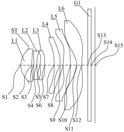
[0086] Please refer to figure 1 , shows a schematic structural view of the optical lens provided by the first embodiment of the present invention, the optical lens along the near optical axis direction from the object side to the image side is as follows: stop ST, first lens L1, second lens L2, the second lens Three lenses L3, a fourth lens L4, a fifth lens L5, a sixth lens L6 and a filter G1.

[0087] The first lens L1 is a plastic aspheric lens with positive refractive power, the object side S1 is convex, and the image side S2 is concave;

[0088] The second lens L2 is a plastic aspheric lens with negative refractive power, the object side S3 is concave at the near optical axis and has an inflection point, and the image side S4 is concave;

[0089] The third lens L3 is a plastic aspheric lens with positive refractive power, the object side S5 is convex at the near optical axis and has an inflection point, and the image side S6 is convex;

[0090] The fourth lens L4 is a pl...

no. 2 example

[0105] Please refer to Image 6 , shows a schematic structural view of the optical lens provided by the second embodiment of the present invention, the optical lens along the near optical axis direction from the object side to the image side is as follows: stop ST, the first lens L1, the second lens L2, the second lens Three lenses L3, a fourth lens L4, a fifth lens L5, a sixth lens L6 and a filter G1.

[0106] The first lens L1 is a plastic aspheric lens with positive refractive power, the object side S1 is convex, and the image side S2 is concave;

[0107] The second lens L2 is a plastic aspheric lens with negative refractive power, the object side S3 is concave at the near optical axis and has an inflection point, and the image side S4 is concave;

[0108] The third lens L3 is a plastic aspheric lens with positive refractive power, the object side S5 is convex at the near optical axis and has an inflection point, and the image side S6 is concave at the near optical axis an...

no. 3 example

[0124] Please refer to Figure 11 , shows a schematic structural view of the optical lens provided by the third embodiment of the present invention, the optical lens along the near optical axis direction from the object side to the image side in turn: stop ST, first lens L1, second lens L2, second lens L2 Three lenses L3, a fourth lens L4, a fifth lens L5, a sixth lens L6 and a filter G1.

[0125] The first lens L1 is a plastic aspheric lens with positive refractive power, the object side S1 is convex, and the image side S2 is concave;

[0126] The second lens L2 is a plastic aspheric lens with positive refractive power, the object side S3 is convex, and the image side S4 is concave;

[0127] The third lens L3 is a plastic aspheric lens with positive refractive power, the object side S5 is convex at the near optical axis and has an inflection point, and the image side S6 is concave at the near optical axis and has an inflection point;

[0128] The fourth lens L4 is a plastic...


PUM


Abstract

The invention provides an optical lens, comprising six lenses in total, including: a diaphragm from the object side to the image side along the optical axis; a first lens with positive refractive power, the object side is convex, the image side is concave; The second lens with optical power has a concave image side; the third lens with optical power has a convex object side at the near optical axis; the fourth lens with optical power has a concave object side and an image side It is convex; the fifth lens with positive refractive power has a convex surface at the near optical axis; the sixth lens with negative refractive power has a concave object side at the near optical axis, and the image side is at the near optical axis is concave; filter. The optical lens provided by the present invention has a compact structure by reasonably matching the surface shape, focal power and placement position of each lens, realizes the miniaturization of the large aperture lens and high pixel balance, and greatly improves the user's camera experience.

Description

technical field [0001] The invention relates to the technical field of molding equipment, in particular to an optical lens. Background technique [0002] At present, with the rapid development of portable electronic products, people's daily life has been greatly facilitated. Even if they are thousands of miles away, they can watch the effect as if they were on the scene at a close distance, such as today's remote conferences, webcasts, security Surveillance, video telephony, and vehicle images are all captured by optical lenses and converted into electrical signals by equipment to complete transmission. With the continuous development of design level and manufacturing technology, people's demand for photography is more extensive and more The more compact and high-performance optical lenses are urgently needed. [0003] However, with the continuous update and development of mobile information technology, electronic devices such as smart phones are developing in the direction...

Claims


Application Information

Patent Timeline
Patent Type & Authority Patents(China)
IPC IPC(8): G02B13/00G02B13/18G03B30/00
CPCG02B13/0045G02B13/18G03B30/00
Inventor 章彬炜熊儒韬曾昊杰曾吉勇
Owner JIANGXI LIANYI OPTICS CO LTD
Why Eureka
Try Eureka