
Terminal connection structure and electric appliance

A terminal connection and terminal connection technology, which is applied in the direction of connection and connection device components, circuits, etc., can solve the problems of cable arrangement, fixing and connection structure complexity, terminal connection structure installation and connection easy to loosen, etc., to achieve Reduce the effect of cable fixing structure, simple structure, and simple fixing structure

Pending Publication Date: 2020-05-22
GREE ELECTRIC APPLIANCES INC
View PDF0 Cites 0 Cited by
  • Summary
  • Abstract
  • Description
  • Claims
  • Application Information

AI Technical Summary

Problems solved by technology

[0002] The cables inside the existing electrical appliances are often arranged along the set wiring trough, and the cables are fixed by the fixed wire structure, and the aerial docking connector is used as the terminal connection structure to realize the connection of the cables. , The fixing and connection structure is complex, in addition, the installation and connection of the terminal connection structure are easy to loosen

Method used


Image

  • Terminal connection structure and electric appliance
  • Terminal connection structure and electric appliance
  • Terminal connection structure and electric appliance

Examples


Embodiment Construction

[0031] Example of terminal connection structure:

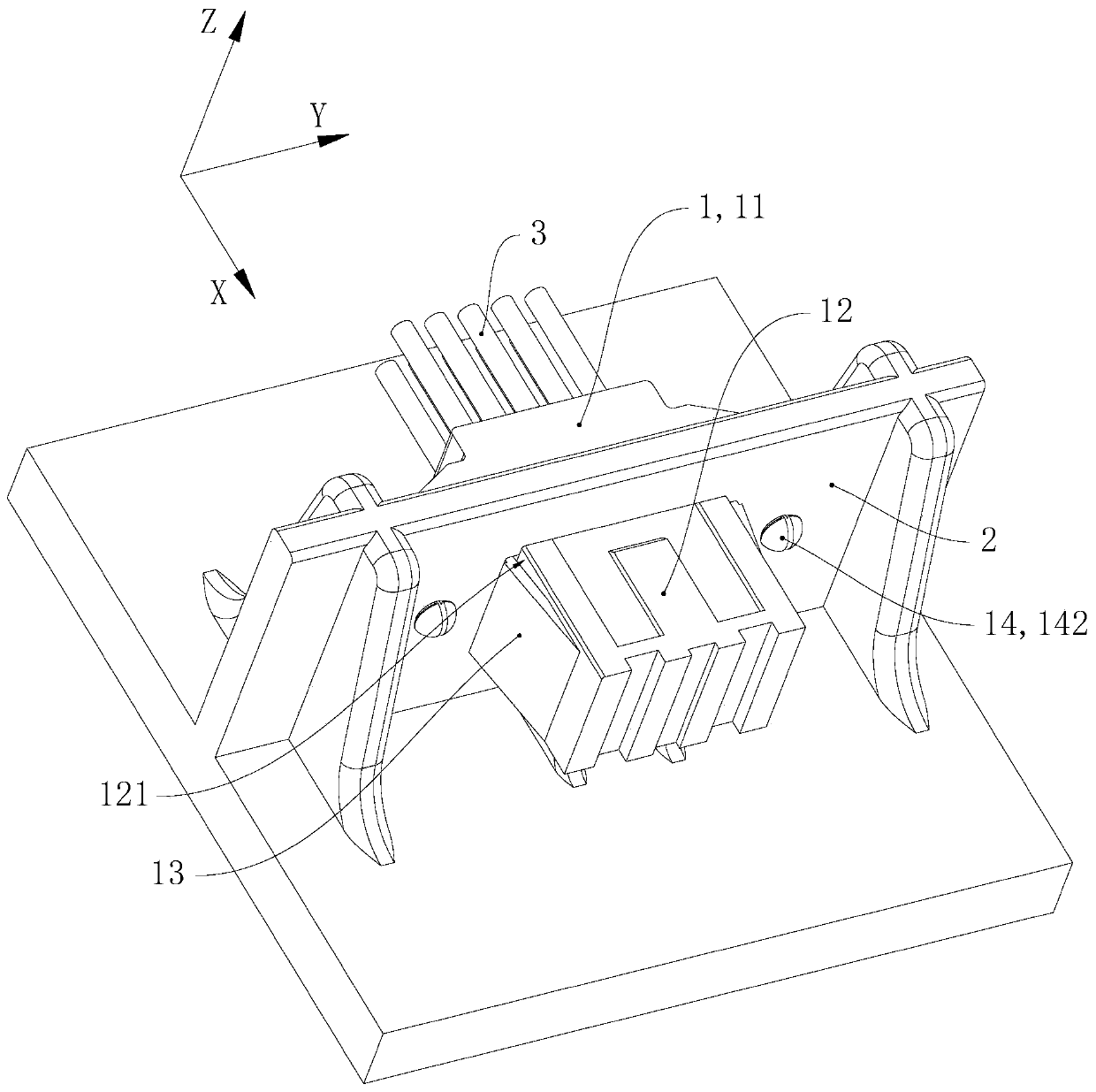
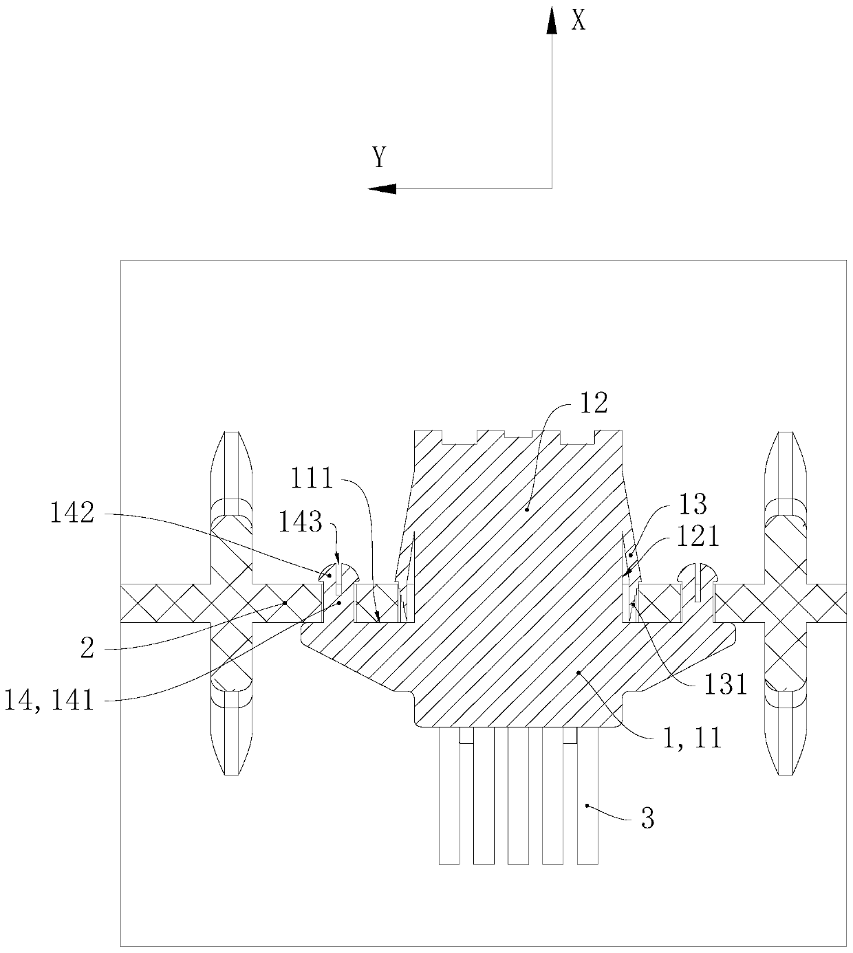
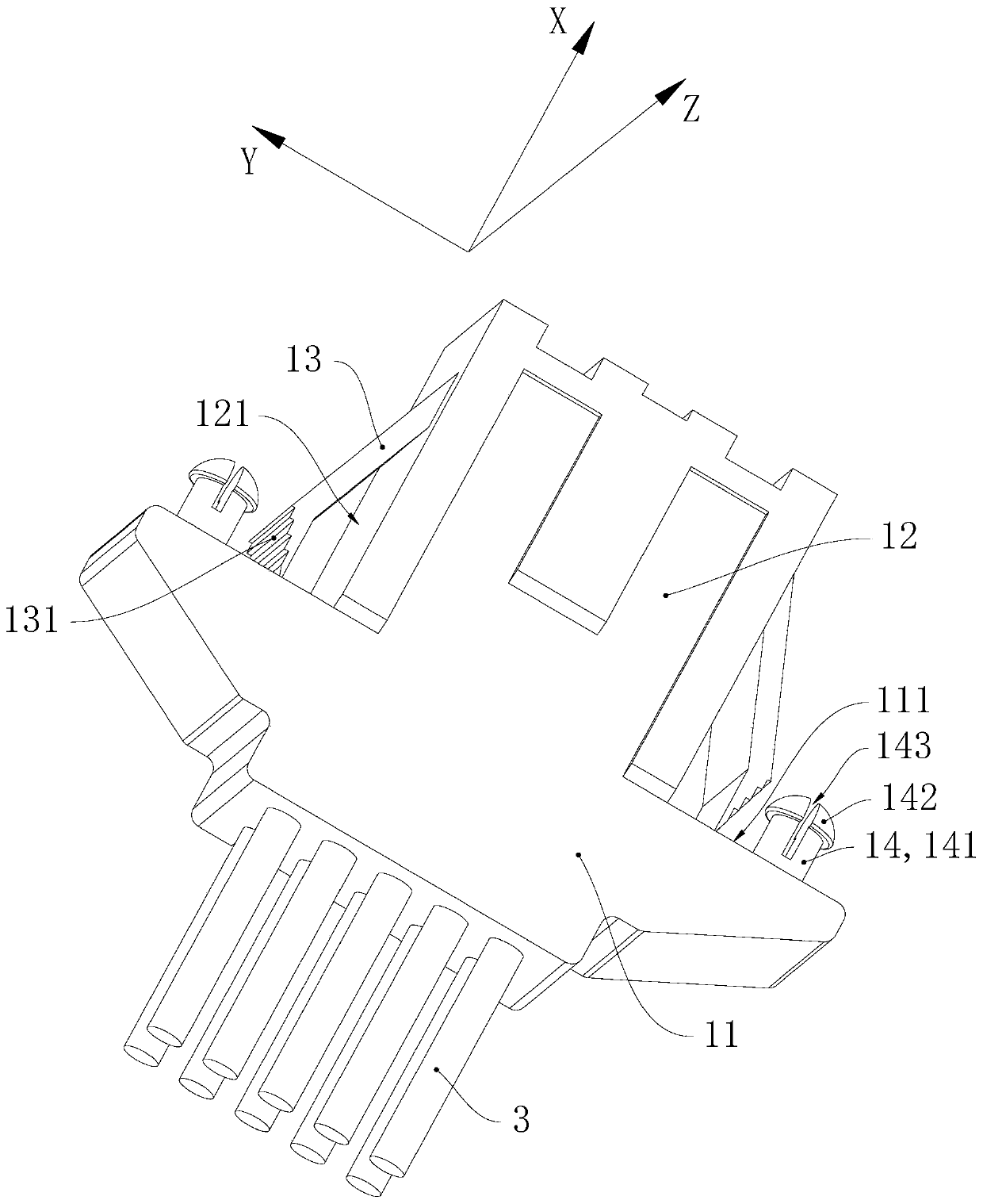
[0032] In this embodiment Figure 1 to Figure 5 A unified spatial Cartesian coordinate system is adopted in the present embodiment to represent the azimuth relationship of each component in the terminal connection structure. The positive direction of the X-axis in this embodiment is the first direction, and the direction of the Y-axis in this embodiment is the second direction.

[0033] Please refer to figure 1 , figure 2 and Figure 4 , the terminal connection structure of this embodiment includes a connection terminal 1 and a mounting plate shell 2, the thickness direction of the mounting plate shell 2 is along the X-axis direction, and the mounting plate shell 2 has an insertion hole 21 and two back-stop holes 22. Both the hole 21 and the stop hole 22 pass through the mounting plate shell 2 along the X-axis direction, and the insertion hole 21 is located between the two stop holes 22 along the Y-axis direction.

[0034...


PUM


Abstract

The invention relates to the field of electric appliances. A terminal connection structure comprises an installation plate shell and a connection terminal, the installation plate shell is provided with an insertion hole and a retaining hole, and the connection terminal is inserted into the insertion hole. The connecting terminal is provided with a base part, a plugging main body part, a card plugging retaining pin and an elastic overhanging part; the plug-in main body part and the plug-in card retaining pin extend out from the base part along a first direction, the front end of the elastic overhanging part is connected with the plug-in main body part along the first direction, the rear end of the elastic overhanging part and the plug-in main body part are distributed at an interval, the plug-in main body part and the elastic overhanging part are both inserted into the plug-in hole, and the elastic overhanging part abuts against the side wall; and the card inserting retaining pin comprises an extending portion and a hook portion, the extending portion extends out of the base portion in the first direction, the hook portion is connected with the extending portion, the card insertingextending portion is inserted into the retaining hole, and the hook portion is limited on the front side of the installation plate shell. The number of fixing structures of the cable is reduced, shaking of the connecting terminal is avoided, and stable and firm connection between the connecting terminal and the mounting plate shell is facilitated.

Description

technical field [0001] The invention relates to the field of electrical appliances, in particular to a terminal connection structure and electrical appliances. Background technique [0002] The cables inside the existing electrical appliances are often arranged along the set wiring trough, and the cables are fixed by the fixed wire structure, and the aerial docking connector is used as the terminal connection structure to realize the connection of the cables. , The fixing and connection structure is complex, and in addition, the installation and connection of the terminal connection structure are easy to loosen. Contents of the invention [0003] One of the objectives of the present invention is to provide a terminal connection structure that is conducive to stable and reliable connection and simple wiring structure. [0004] In order to achieve the above object, the terminal connection structure provided by the present invention includes a mounting plate shell and a conn...

Claims


Application Information

Patent Timeline
Patent Type & Authority Applications(China)
IPC IPC(8): H01R13/426H01R13/46
CPCH01R13/426H01R13/46
Inventor 梁翠飞陈荣华孙小洪杨登明王高敏黄江江
Owner GREE ELECTRIC APPLIANCES INC
Learn More