Slicer cutting area wire net center adjusting device and adjusting method

A technology of wire mesh center and cutting area, which is applied in the direction of fine working devices, working accessories, manufacturing tools, etc., can solve the problems that the rotation center distance cannot be adjusted, affects the cutting yield, and limits the cutting capacity of the slicer, etc., to achieve improved cutting effect of ability

Pending Publication Date: 2020-05-26
QINGDAO GAOCE TECH CO LTD
View PDF0 Cites 2 Cited by
  • Summary
  • Abstract
  • Description
  • Claims
  • Application Information

AI Technical Summary

Problems solved by technology

In actual production, the rotation center distance between the supporting rollers cannot be adjusted, which limits the cutting capacity of the slicer and affects the cutting yield

Method used


Image

  • Slicer cutting area wire net center adjusting device and adjusting method
  • Slicer cutting area wire net center adjusting device and adjusting method
  • Slicer cutting area wire net center adjusting device and adjusting method

Examples


Embodiment 1

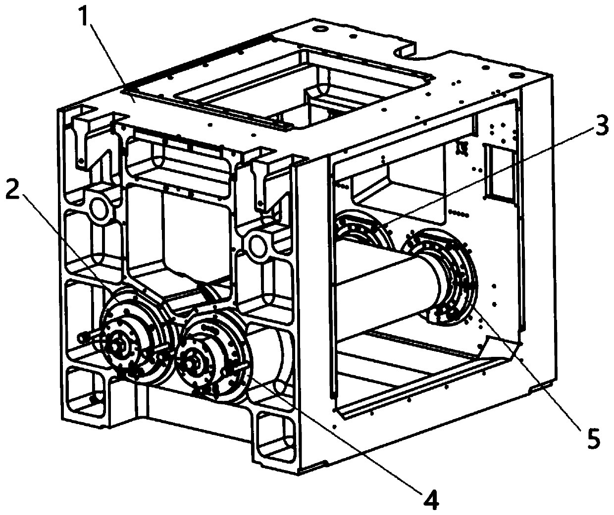
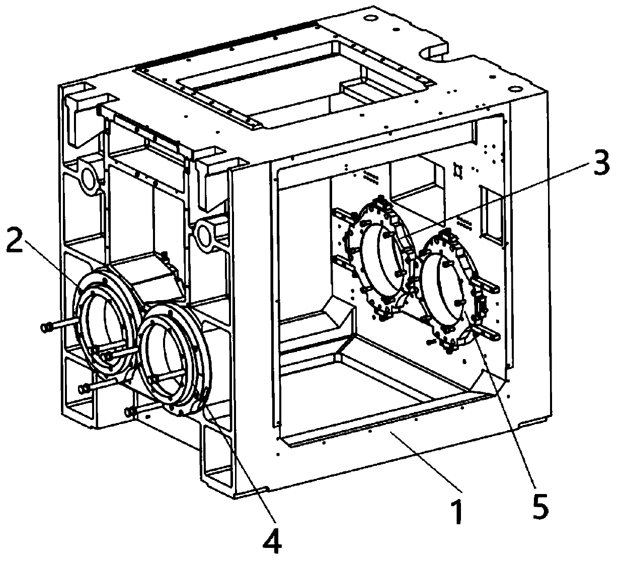
[0027] see figure 1 , figure 2 , the present invention adjusts the device of slicer cutting area line net center, and this device is arranged at the cutting area of ​​slicer, comprises frame 1, and frame 1 front side offers first front inner hole and second front inner hole, meanwhile, frame 1 The rear side is provided with a first rear inner hole and a second rear inner hole.

[0028] In this embodiment, the centers of the first front inner hole and the first rear inner hole are optimally on the same axis, and similarly, the centers of the second front inner hole and the second rear inner hole are optimally on the same axis.

[0029] A first eccentric support roller is arranged between the first front inner hole and the first rear inner hole, and a second eccentric support roller is arranged between the second front inner hole and the second rear inner hole. The first eccentric support roller is composed of a first eccentric sleeve assembly, a first bearing box assembly an...

Embodiment 2

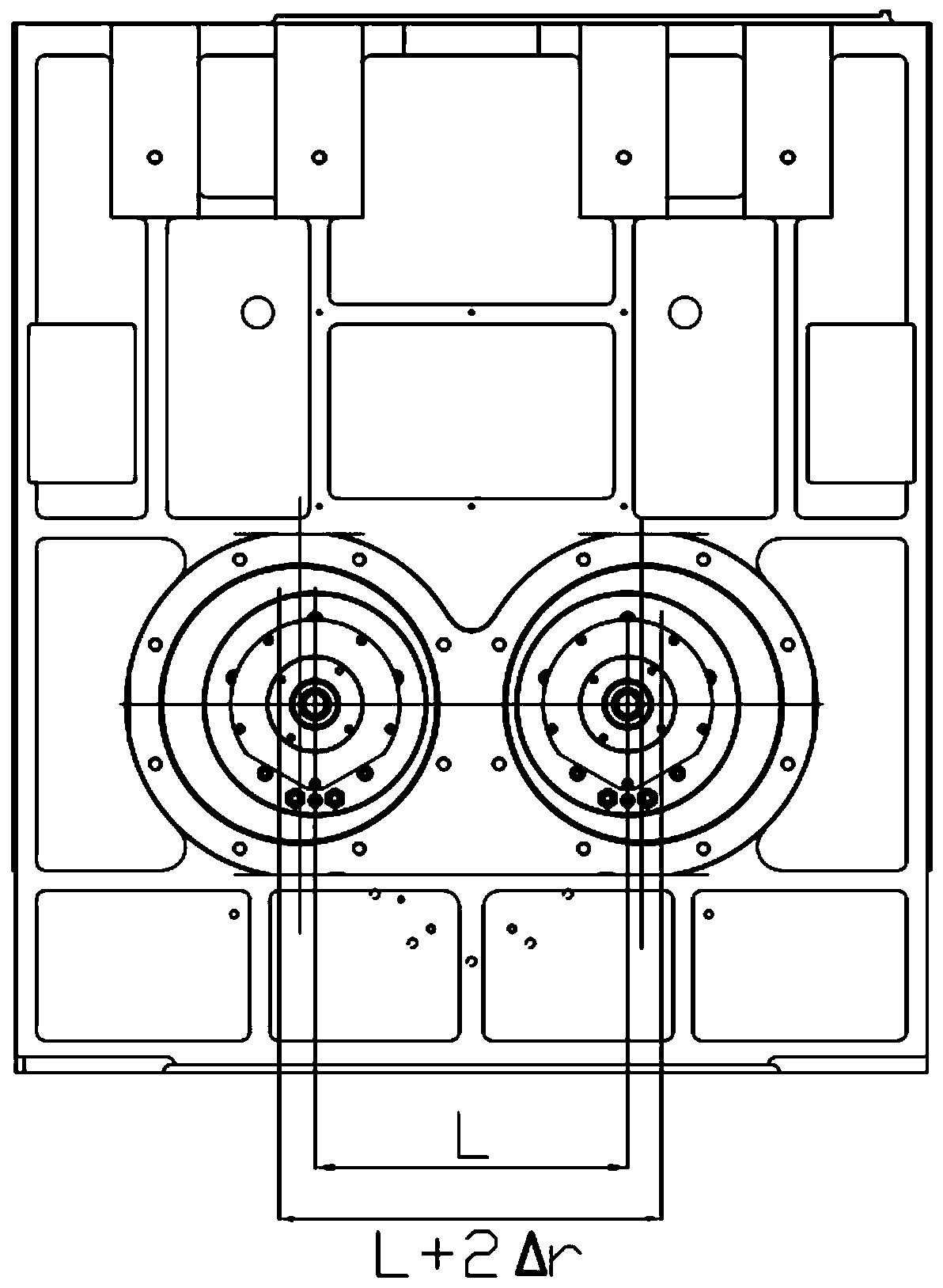
[0035] see Figure 4 , Another embodiment of the device for adjusting the wire mesh center in the cutting area of ​​the slicer according to the present invention is different from Embodiment 1 in that the first eccentric support roller is composed of the first eccentric bearing box assembly and the first main roller. The second eccentric support roll is composed of the second eccentric bearing box assembly and the second main roll.

[0036] The first eccentric bearing box assembly includes the first front eccentric bearing box 6 and the first rear eccentric bearing box 7, the first front eccentric bearing box 6 is fixed in the first front inner hole, and the first rear eccentric bearing box 7 is fixed in the first In the posterior inner hole. The first main roller is arranged between the first front eccentric bearing box 6 and the first rear eccentric bearing box 7 .

[0037] The second eccentric bearing box assembly includes a second front eccentric bearing box 8 and a seco...


PUM


Abstract

The invention belongs to the technical field of slicers, and particularly relates to a slicer cutting area wire net center adjusting device. The slicer cutting area wire net center adjusting device comprises a frame, a first front inner hole and a second front inner hole are formed in the front side of the frame, a first rear inner hole and a second rear inner hole are formed in the rear side of the frame, a first eccentric supporting roller is arranged between the first front inner hole and the first rear inner hole, and a second eccentric supporting roller is arranged between the second front inner hole and the second rear inner hole. The invention further relates to an adjusting method of the center distance of the wire net, the first eccentric supporting roller and the second eccentricsupporting roller are fixed in the frame, and the center distance of the wire net in the cutting area is changed by adjusting the rotating center distance between the two eccentric supporting rollers. According to the slicer cutting area wire net center adjusting device and the adjusting method, the eccentric supporting rollers are arranged, the problem that the rotating center distance of the two supporting rollers cannot be adjusted is well solved, the rotating center distance of the supporting rollers can be adjusted within a certain range, hard and brittle materials of different sizes canbe cut through single equipment, and the cutting capacity of a slicer is improved to a great extent.

Description

technical field [0001] The invention belongs to the technical field of slicing machines, and in particular relates to a device and an adjusting method for adjusting the wire net center in a cutting area of ​​a slicing machine. Background technique [0002] In the actual production process, the actual cutting capacity of the slicer is mainly related to the width of the wire mesh in the cutting area. The smaller the wire mesh width, the smaller the size of hard and brittle materials that can be cut; the larger the wire mesh width, the larger the size of hard and brittle materials that can be cut. However, when the size of the hard and brittle material is small, the smaller the width of the wire mesh under the cutting conditions, the better the cutting yield, and the yield rate will decrease as the width of the wire mesh increases. Therefore, hard and brittle materials of different sizes need to be cut with wire meshes of corresponding widths to achieve the best yield. In act...

Claims


Application Information

Patent Timeline
Patent Type & Authority Applications(China)
IPC IPC(8): B28D1/22B28D5/04B28D7/00
CPCB28D1/22B28D5/0058B28D5/045B28D7/00
Inventor 张璐袁康孙承政周波陈俊儒范国强宫云庆于云飞庄旭升
Owner QINGDAO GAOCE TECH CO LTD
Why Eureka
Try Eureka