Light guide plate and backlight module

A technology of backlight module and light guide plate, which is applied in the direction of light guide, optics, optical components, etc., can solve the problem of uneven light source and achieve good optical performance and good optical quality

Active Publication Date: 2020-05-26
NANO PRECISION TAIWAN LTD
View PDF6 Cites 7 Cited by
  • Summary
  • Abstract
  • Description
  • Claims
  • Application Information

AI Technical Summary

Problems solved by technology

However, since the light of this kind of light guide plate needs to go through the collimated microstructure many times before it can emit light from the light guide plate, the closer to the light incident side of the light guide plate, the less light can be emitted, and the light on the light incident side of the light guide plate A dark band area is formed, which leads to uneven surface light source provided by the light guide plate

Method used


Image

  • Light guide plate and backlight module
  • Light guide plate and backlight module
  • Light guide plate and backlight module

Examples


Embodiment Construction

[0021] The aforementioned and other technical contents, features and effects of the present invention will be clearly presented in the following detailed description of a preferred embodiment with reference to the accompanying drawings. The directional terms mentioned in the following embodiments, such as: up, down, left, right, front or back, etc., are only referring to the directions of the drawings. Accordingly, the directional terms are used to illustrate and not to limit the invention.

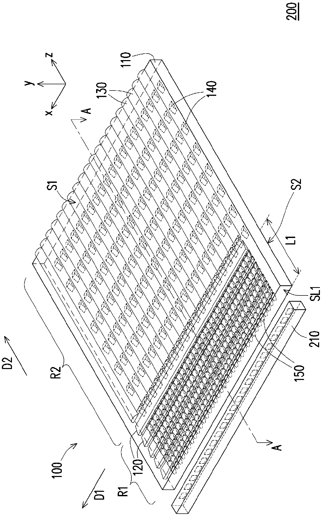
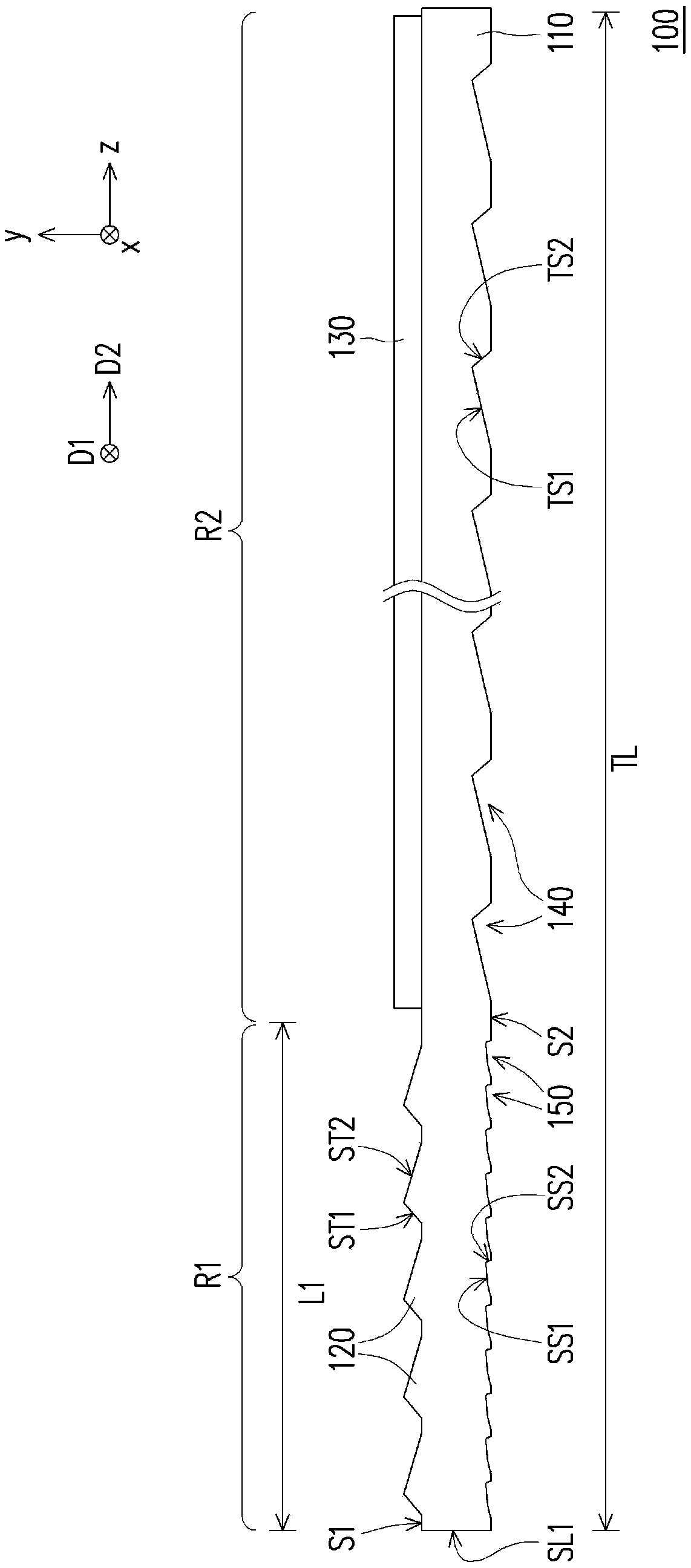
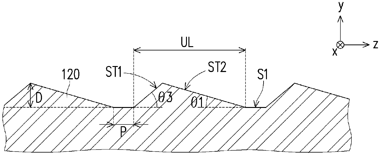
[0022] Figure 1A It is a structural schematic diagram of a backlight module according to an embodiment of the present invention. Figure 1B yes Figure 1A The schematic cross-sectional view of the light guide plate along the line A-A. Please refer to Figure 1A and Figure 1B , the backlight module 200 of this embodiment includes a light guide plate 100 and a light source 210 . For example, in this embodiment, the light source 210 may be a light bar including a plurality of light emit...


PUM

PropertyMeasurementUnit
lengthaaaaaaaaaa
sizeaaaaaaaaaa
sizeaaaaaaaaaa

Abstract

The invention discloses a light guide plate and a backlight module. The light guide plate is provided with a first area and a second area and comprises a plate body, a plurality of first strip-shapedmicrostructures, a plurality of prism-shaped microstructures and a plurality of light scattering microstructures. The plate body is provided with a first surface, a second surface and a first side surface which are opposite to each other, and the first area is closer to the first side surface than the second area. The first strip-shaped microstructures are formed on the first surface and located in the first area. The first strip-shaped microstructure extends along a first direction parallel to the first side surface. The prism-shaped microstructure is recessed into the second surface and is located in the second region. Each prism-shaped microstructure is provided with a first inclined surface facing the first side surface. The light scattering microstructure is recessed into the second surface and is located in the first region. The backlight module comprises the light guide plate. The light guide plate and the backlight module have good optical performance.

Description

technical field [0001] The present invention relates to a light guide plate and a backlight module, and in particular to a light guide plate and a backlight module with a collimation microstructure. Background technique [0002] Current electronic devices mostly use flat panel display modules to display images, among which the technology of liquid crystal display modules is relatively sophisticated and popular. However, since the display panel of the liquid crystal display module itself cannot emit light, a backlight module is provided under the display panel to provide light required for displaying images. Backlight modules can be mainly divided into edge-type backlight modules and direct-type backlight modules. The edge-lit backlight module utilizes the light guide plate to guide the light emitted by the light source disposed on the light incident side of the light guide plate to the light output surface of the light guide plate, thereby forming a surface light source. G...

Claims


Application Information

Patent Timeline
Patent Type & Authority Applications(China)
IPC IPC(8): G02B6/00
CPCG02B6/0016G02B6/0036
Inventor 邱文彦
Owner NANO PRECISION TAIWAN LTD
Why Eureka
Try Eureka