Rotary shaft punching device

A punching device and shaft technology, which is applied in metal processing and other directions, can solve the problems of inconvenient clamping and fixing of different types of shafts, poor fixing effect, and inability to drill holes on the shaft, so as to meet the needs of daily use and facilitate clamping and fixing , Improve the effect of punching effect

Inactive Publication Date: 2020-05-29
南京路博利尔精密机械有限公司
View PDF0 Cites 2 Cited by
  • Summary
  • Abstract
  • Description
  • Claims
  • Application Information

AI Technical Summary

Problems solved by technology

[0003] The purpose of the present invention is to solve the disadvantages in the prior art that it is inconvenient to clamp and fix different types of rotating shafts, and at the same time the fixing effect is poor, and it is impossible to punch holes at different positions of the rotating shaft, and proposes a rotating shaft punching device

Method used


Image

  • Rotary shaft punching device
  • Rotary shaft punching device
  • Rotary shaft punching device

Examples


Embodiment Construction

[0020] The following will clearly and completely describe the technical solutions in the embodiments of the present invention with reference to the accompanying drawings in the embodiments of the present invention. Obviously, the described embodiments are only some, not all, embodiments of the present invention.

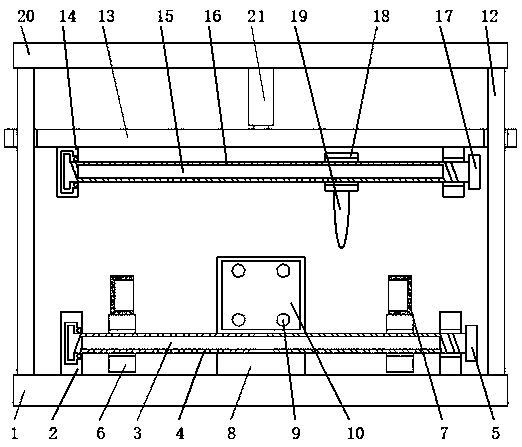
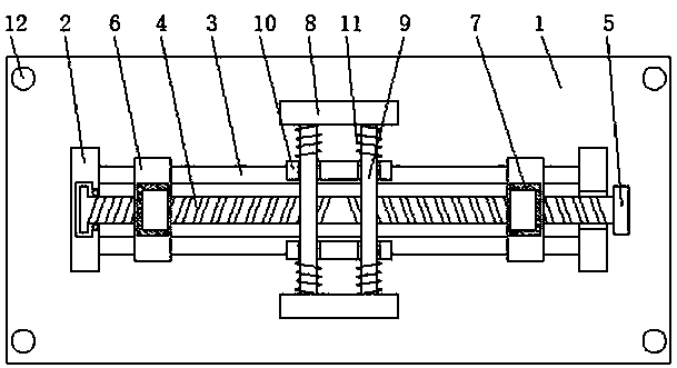
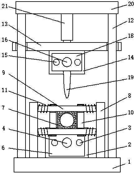
[0021] refer to Figure 1-3 , a rotary shaft punching device, including a base 1, vertical plates 2 are fixed on both sides of the top of the base 1, two sets of cross bars 3 are fixed between the vertical plates 2, and two-way screw threads placed horizontally are arranged between the cross bars 3 Rod 4, two sets of moving plates 6 are threadedly connected on the two-way threaded rod 4, baffle plates 8 are fixed on the other two sides of the top of the base 1, four groups of guide rods 9 are fixed between the two groups of baffle plates 8, and on the guide rods 9 Two groups of movable plates 10 are slidingly connected, and two groups of springs 11 are sleeved on the...


PUM


Abstract

The invention discloses a rotary shaft punching device. The rotary shaft punching device comprises a base. Vertical plates are fixed to the two sides of the top end of the base. Two sets of cross rodsare fixed between the two vertical plates. Bidirectional threaded rods arranged horizontally are arranged between the corresponding cross rods. One bidirectional threaded rod is in threaded connection with two movable plates. Baffles are fixed to the other two sides of the top end of the base. Four guide rods are fixed between the two baffles. Two movable plates are slidably connected to the guide rods. The outer portion of each guide rod is sleeved with two springs. The springs are located between the baffles and the movable plates. Vertical rods are fixed to the four sides of the top end ofthe base. The rotary shaft punching device is ingenious in design, compact in structure and easy to operate and can be used for clamping and fixing the two ends of different types of rotary shafts conveniently. Thus, the application range of the rotary shaft punching device can be expanded. Meanwhile, the clamping and fixing effect of the rotary shaft punching device on the rotary shafts can be enhanced. The rotary shaft punching device can punch a hole in any position of each rotary shaft conveniently, can meet daily usage requirements of people and is high in flexibility and beneficial to improving the punching effect.

Description

technical field [0001] The invention relates to the technical field of rotating shaft drilling, in particular to a rotating shaft drilling device. Background technique [0002] The rotating shaft, as the name implies, is the shaft that must be used to connect the main parts of the product and is used to bear both bending moment and torque in the rotating work. The shaft that must be used for the main parts of the linked product parts and is used to bear both bending moment and torque in the rotating work is called the rotating shaft. Common shafts are: mobile phone shaft (clamshell or rotating screen mobile phone); laptop shaft; portable DVD shaft; LED desk lamp shaft; LCD display shaft; GPS and other car bracket shafts, etc. In the existing production process of the rotating shaft, the rotating shaft needs to be drilled, and the rotating shaft needs to be fixed during the drilling process, but the traditional punching device is not convenient for clamping and fixing differ...

Claims


Application Information

Patent Timeline
Patent Type & Authority Applications(China)
IPC IPC(8): B26F1/24B26D7/02B26D7/26
CPCB26D7/02B26D7/2628B26D2007/013B26F1/24
Inventor 不公告发明人
Owner 南京路博利尔精密机械有限公司
Why Eureka
Try Eureka