
Electric vehicle torque control method and electronic equipment

A technology of torque control and electric vehicles, applied in electric vehicles, control drives, control devices, etc., can solve the problems affecting the driver's comfort, lack of motor torque correction, etc., and achieve the effect of comfortable acceleration

Active Publication Date: 2020-05-29
恒大恒驰新能源汽车科技(广东)有限公司
View PDF8 Cites 15 Cited by
  • Summary
  • Abstract
  • Description
  • Claims
  • Application Information

AI Technical Summary

Problems solved by technology

[0004] Based on this, it is necessary to provide an electric vehicle torque control method and electronic equipment for the technical problem that the existing technology only determines the motor torque by querying the motor torque table and lacks correction of the motor torque, thus affecting the driver's comfort.

Method used


Image

  • Electric vehicle torque control method and electronic equipment
  • Electric vehicle torque control method and electronic equipment
  • Electric vehicle torque control method and electronic equipment

Examples


Embodiment 2

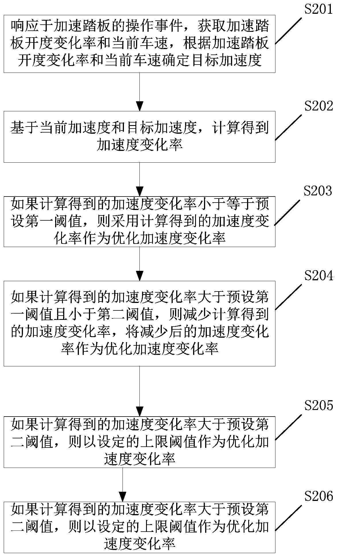
[0054] Such as figure 2 Shown is a working flow chart of an electric vehicle torque control method according to one embodiment of the present application, including:

[0055] Step S201, in response to the operation event of the accelerator pedal, obtain the rate of change of the opening of the accelerator pedal and the current vehicle speed, and determine the target acceleration according to the rate of change of the opening of the accelerator pedal and the current vehicle speed;

[0056] Step S202, based on the current acceleration and the target acceleration, calculate the acceleration change rate;

[0057]Step S203, if the calculated jerk is less than or equal to the preset first threshold, then use the calculated jerk as the optimized jerk;

[0058] Step S204, if the calculated jerk is greater than the preset first threshold and smaller than the second threshold, then reduce the calculated jerk, and use the reduced jerk as the optimized jerk;

[0059] The reduced jerk r...

Embodiment 3

[0071] Such as Figure 6 Shown is a working flow chart of an electric vehicle torque control method according to one embodiment of the present application, including:

[0072] Step S601, setting the accelerometer under steady state;

[0073] According to relevant research, the driver operates the accelerator pedal and expects to obtain a suitable acceleration. The expected acceleration is different under different accelerator pedal openings and different vehicle speeds. According to theoretical analysis and test statistics, set the accelerometer shown in Table 1:

[0074]

[0075] Step S602, identifying the rate of change of the opening of the accelerator pedal, and setting the rate of change of the acceleration accordingly;

[0076] Specifically, according to the rate of change of the opening of the accelerator pedal and the interpolation calculation of the accelerometer in step S601, the target acceleration and the rate of change of the acceleration are obtained;

[00...


PUM


Abstract

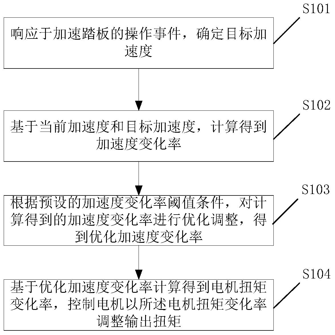
The invention discloses an electric vehicle torque control method and electronic equipment, and the method comprises the steps: determining a target acceleration in response to an operation event of an accelerator pedal; calculating an acceleration change rate based on the current acceleration and the target acceleration; optimizing and adjusting the calculated acceleration change rate according to a preset acceleration change rate threshold condition to obtain an optimized acceleration change rate; and calculating to obtain a motor torque change rate based on the optimized acceleration changerate, and controlling the motor to adjust the output torque according to the motor torque change rate. According to the invention, the acceleration change rate is corrected, so that the adjustment ofthe motor torque better meets the comfort level of a human body. By the adoption of the motor torque control strategy, a driver can obtain a more comfortable acceleration feeling when rapidly stepping on the accelerator pedal, cannot feel impact and cannot feel obvious power delay.

Description

technical field [0001] The present application relates to the technical field of automobile-related technologies, in particular to an electric vehicle torque control method and electronic equipment. Background technique [0002] When the driver in the electric vehicle performs tip-in (quick accelerator pedal operation), the motor torque is determined by the current accelerator pedal opening and the motor speed, and is determined by looking up the motor torque table. The current motor torque table is based on experience and actual vehicle calibration, and its calibration results depend on the experience and subjective evaluation level of the calibration engineer, which cannot reflect the most comfortable and ideal needs of the driver. Therefore, the rising curve of the motor torque when the opening of the accelerator pedal is increased is only calibrated based on experience and subjective evaluation, and cannot be adjusted according to the comfort of the driver. [0003] At ...

Claims


Application Information

Patent Timeline
Patent Type & Authority Applications(China)
IPC IPC(8): B60L15/20
CPCB60L15/20B60L2240/14B60L2240/423Y02T10/72
Inventor 范良明
Owner 恒大恒驰新能源汽车科技(广东)有限公司
Learn More