
Construction method of assembly and launch in shield tunnel

A technology of shield tunneling and construction method, which is applied in the direction of tunnels, tunnel linings, shaft equipment, etc., can solve the problems of occupying social living space, long construction period, and large-scale demolition, so as to avoid large-scale demolition, reduce actual consumption, The effect of avoiding technical risks

Active Publication Date: 2021-03-02
中铁二院重庆勘察设计研究院有限责任公司
View PDF6 Cites 0 Cited by
  • Summary
  • Abstract
  • Description
  • Claims
  • Application Information

AI Technical Summary

Problems solved by technology

First of all, the shaft needs to be located at a suitable location on the river bank and directly above the access path. At the same time, a stock yard should be set up. In mountainous cities, it will be adjacent to municipal dense buildings or high-rise buildings, and it will occupy limited social living space for a long time, or cause large-scale demolition. , will lead to high construction costs and social operating costs
Secondly, the elevation of the cross-river tunnel needs to be lower than a certain height of the water body in order to reduce construction and environmental safety risks. However, if a shaft is installed on a mountainous river bank, its depth will inevitably be very large, which will also affect the safety of adjacent structures, and the design and construction technology control is difficult. High risk; construction slag discharge, low feed efficiency, long construction period, or delay in construction period; inconvenient operation and management, high cost

Method used


Image

  • Construction method of assembly and launch in shield tunnel
  • Construction method of assembly and launch in shield tunnel
  • Construction method of assembly and launch in shield tunnel

Examples


Embodiment Construction

[0033] The following are specific embodiments of the present invention and in conjunction with the accompanying drawings, the technical solutions of the present invention are further described, but the present invention is not limited to these embodiments.

[0034] The construction method of assembling and starting in the shield tunnel hole comprises the following steps:

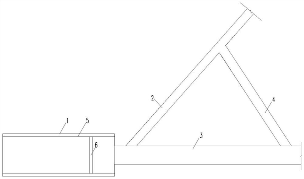
[0035] ① On the starting shore, design and assemble the starting cavern 1, the inclined shaft 2, the branch tunnel 4 and the main line tunnel 3 in combination with the engineering needs and the shield tunneling needs. Design requirements: such as figure 1 As shown, the front end and assembly of the main line tunnel 3 are docked with the rear end of the starting cavern 1, the inclined shaft 2 is connected to the main line tunnel 3 at a plane intersection angle of 30°-60°, and the slope of the inclined shaft 2 is not greater than 10%; The branch tunnel 4 is connected to the main line tunnel 3 at a plane inter...


PUM


Abstract

The invention provides a construction method of assembling and starting in a shield tunnel hole. The problems that for construction of an existing shield method, a design and construction technology is large in control difficulty, and the risk is high can be solved. The method comprises the following steps that a borehole-blasting method is adopted for finishing inclined shaft, branch hole, main line tunnel and assembling and starting hole chamber construction; a transport vehicle conveys a shield cutterhead, a shield body, a counterforce frame, steel inclined struts and the like to the assembling and starting hole chamber through an inclined shaft, and assembling and turnover of the shield cutterhead, assembling of the shield body and manufacturing and splicing of the counterforce frame are finished; with the same method, after-shield matching parts are transported to the assembling and starting hole chamber to be assembled, and are drawn to the main line tunnel to be stored; the after-shield matching parts are connected with the shield body, and whole machine assembling and debugging are finished; and during beginning, pipe segments are conveyed in from the branch holes, after all the after-shield matching parts pass through a crossing opening of the inclined shaft and the main line tunnel, and the pipe segments are conveyed in from the inclined shaft until a shield section is constructed. Construction is convenient, the flow is simple and clear, economic and social benefits are high, and the wide application prospects are achieved.

Description

technical field [0001] The invention belongs to the technical field of civil tunnel engineering, and relates to a construction method for assembling and launching in a shield tunnel. Background technique [0002] With the development of national construction, traffic and other functional paths crossing the river in the form of bridges are increasingly restricted by urban architecture, municipal engineering and waterway management, while crossing rivers, fjords and even straits with tunnels has become a practical achievement and a basic trend. Such as Wuhan Yangtze River Tunnel, Jinan Yellow River Tunnel, Hong Kong-Zhuhai-Macao Cross-sea Tunnel, etc. [0003] In order to ensure the construction safety of the tunnel project, the shield tunneling method is preferred for cross-river tunnel construction. When constructing a cross-river tunnel, the vertical shaft is mainly used as the starting and receiving site, but there are also shortcomings and limitations. First of all, the...

Claims


Application Information

Patent Timeline
Patent Type & Authority Patents(China)
IPC IPC(8): E21D9/06E21D9/14E21D11/08E21D11/40
CPCE21D9/06E21D9/14E21D11/08E21D11/40E21D9/0609
Inventor 陈杨田攀陶伟明杨翔于茂春曹林卫刘保林马洪杨宝吴伟裴昌进
Owner 中铁二院重庆勘察设计研究院有限责任公司
Learn More