
Tunnel coring device

A technology of coring device and tunnel, applied in the direction of sampling device, etc., can solve the problems of slow coring speed, poor coring effect, single function of tunnel coring device, etc., and achieves the effect of convenient processing, low cost and changing structure.

Pending Publication Date: 2020-05-29
陕西鼎盛恒信建筑工程股份有限公司
View PDF0 Cites 1 Cited by
  • Summary
  • Abstract
  • Description
  • Claims
  • Application Information

AI Technical Summary

Problems solved by technology

[0005] The technical problem to be solved by the present invention is that the existing tunnel coring device has single function, slow coring speed and poor coring effect

Method used


Image

  • Tunnel coring device
  • Tunnel coring device

Examples


Embodiment Construction

[0026] The specific implementation manners of the present invention will be further described in detail below in conjunction with the accompanying drawings and embodiments. The following examples are used to illustrate the present invention, but are not intended to limit the scope of the present invention.

[0027] In the description of the present invention, it should be understood that the terms "center", "longitudinal", "transverse", "upper", "lower", "front", "rear", "left", "right", "vertical The orientations or positional relationships indicated by "straight", "horizontal", "top", "bottom", "inner", "outer", etc. are based on the orientation or positional relationship shown in the drawings, and are only for the convenience of describing the present invention and simplifying the description , rather than indicating or implying that the device or element referred to must have a particular orientation, be constructed and operate in a particular orientation, and thus should ...


PUM


Abstract

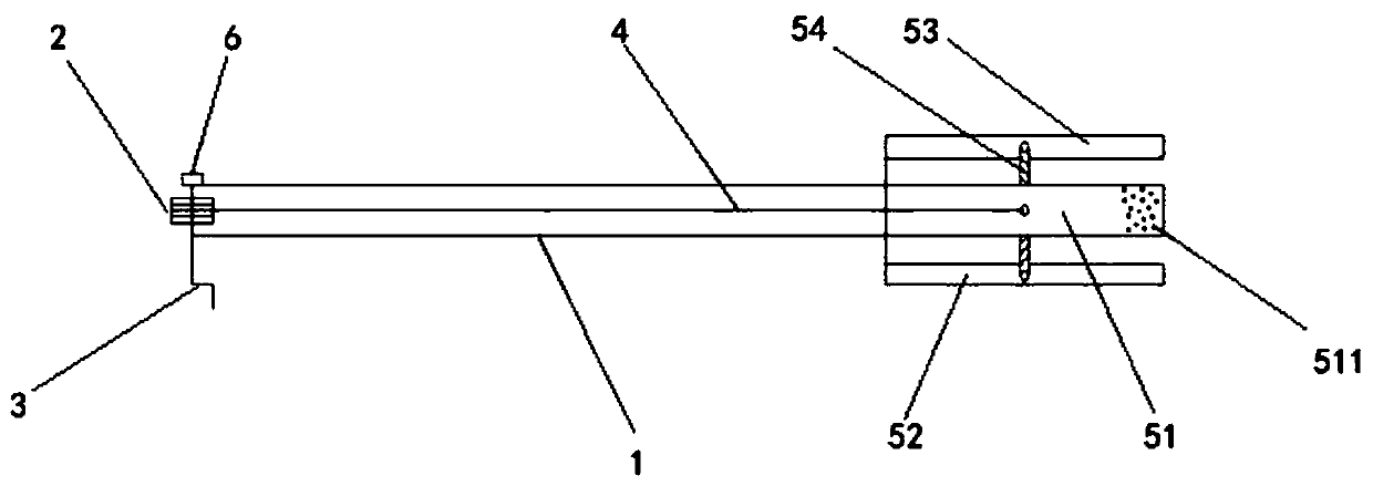
The invention discloses a tunnel coring device which comprises a hand-cranking device, a fixed pulley, a coring device body, a connecting rope and a blade set. The hand-cranking device and the fixed pulley are arranged at the first end of the coring device body. The blade set is arranged at the second end of the coring device body, the connecting rope penetrates through the coring device body, oneend of the connecting rope is wound around the fixed pulley, and the other end of the connecting rope is connected with the blade set. The hand-cranking device is used for rotating the fixed pulley,and the connecting rope is used for controlling the blade set to contract. The tunnel coring device aims to solve the problems that an existing tunnel coring device is single in function, low in coring speed and poor in coring effect.

Description

technical field [0001] The invention belongs to the technical field of engineering equipment, and in particular relates to a tunnel corer. Background technique [0002] Most of the tunnels in the new high-speed railway projects in the northern region are loess tunnels in terms of geology. In order to prevent problems such as arching and sinking of the line in the later operation process, there are certain requirements for the construction technology and construction method of the tunnel inverted arch construction. In addition, an effective way to detect inverted arches is to drill core samples to check thickness, strength, and delamination positions. The diameter of the drilled core sample is 10cm, and the length is from the top surface of the filling to the bottom of the inverted arch according to the design. In the core sample, because the joint of two different grades of concrete poured in layers is the weakest, it is easy to break during the process of extracting the co...

Claims


Application Information

Patent Timeline
IPC IPC(8): G01N1/08
CPCG01N1/08
Inventor 林长宝
Owner 陕西鼎盛恒信建筑工程股份有限公司
Learn More