Wood screw

a wood screw and screw head technology, applied in the field of screws, can solve the problems of ineffective cutting and scraping, poor screwing effect, and inability to achieve good screwing effect, and achieve the effect of better screwing

Inactive Publication Date: 2014-06-26
TAIWAN SHAN YIN INT CO LTD
View PDF4 Cites 12 Cited by
  • Summary
  • Abstract
  • Description
  • Claims
  • Application Information

AI Technical Summary

Benefits of technology

[0008]It is therefore the purpose of this invention to provide a wood screw that effectively scrapes off burrs generates around the drilling hole and provides a space enough for t

Problems solved by technology

1. The wooden board is composed of the resilient wooden fibers. The ribs are defined at intervals. While screwing, because the ribs are defined at intervals and the wood fibers are resilient, the ribs often cannot effectively cut and scrape off burrs generated around the drilling hole 21. Therefore, the

Method used


Image

  • Wood screw
  • Wood screw
  • Wood screw

Examples


Embodiment Construction

[0019]Wherever possible, the same reference numbers are used in the drawings and the description to refer to the same or like parts.

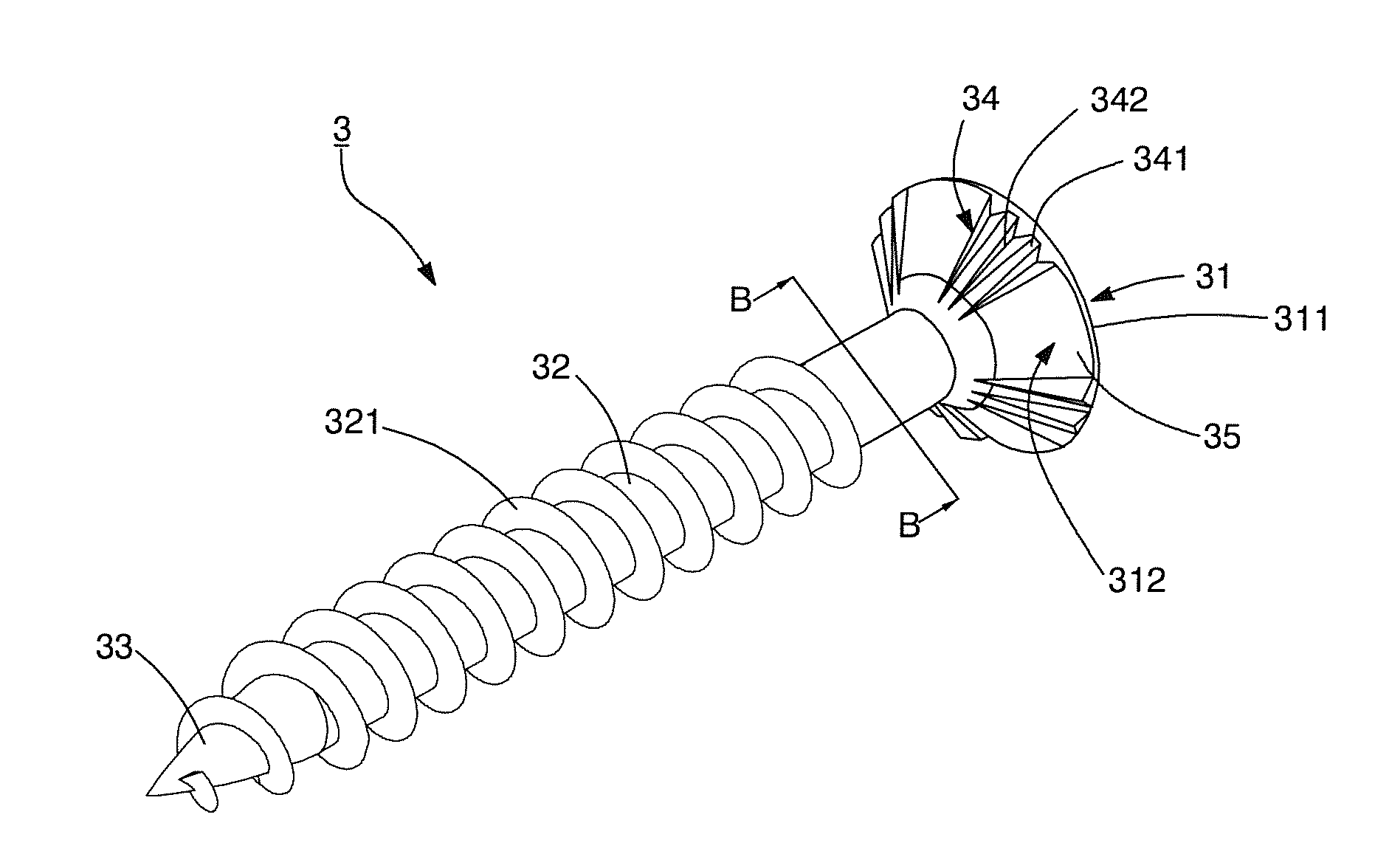
[0020]Referring to FIG. 4, a first preferred embodiment of the present invention is shown. A wood screw 3 comprises a head 31, a shank 32 extending from the head 31, and a drilling portion 33 disposed on a side of the shank 32, opposite to the head 31; wherein, a plurality of threads 321 are spirally disposed on the shank 32 by a certain spiral angle. The head 31 includes a top surface 311 and a conical bottom surface 312 extending downward from the top surface 311. Referring to FIG. 5, the bottom surface 312 includes a plurality of auxiliary cutting areas 34 and a flat area 35 formed between any two adjacent auxiliary cutting areas 34. Each auxiliary cutting area 34 includes at least two cutting grooves 341 disposed at intervals on the bottom surface 312 and a cutting edge 342 formed at a convergence of the two connective cutting grooves 341. In this e...


PUM

PropertyMeasurementUnit
Angleaaaaaaaaaa
Areaaaaaaaaaaa

Abstract

A wood screw provides a plurality of auxiliary cutting areas disposed on a bottom surface of a head and a flat area formed in any two adjacent auxiliary cutting areas. Each auxiliary cutting area includes at least two cutting grooves disposed at intervals and formed on the bottom surface, and a cutting edge formed at a convergence of the connective cutting grooves. When the bottom surface contacts the surface of the wood, the cutting edge cuts and scrapes off burrs generated around the drilling hole, and the scraped burrs are accommodated in the cutting grooves to prevent the burrs from exposing to the head after screwing. Further, the head is tightly screwed on the wood to enhance the screwing stabilization.

Description

BACKGROUND OF THE INVENTION[0001]1. Field of the Invention[0002]The present invention relates to a screw, particularly to a screw used for screwing onto a wooden board.[0003]2. Description of the Related Art[0004]Referring to FIGS. 1 and 2, a conventional wood screw 1 comprises a head 11, a shank 12 extending from the head 11, and a drilling portion 13 disposed on a other side of the shank 12, opposite to the head 11; wherein, a plurality of threads 121 are spirally disposed on the shank 12. The head 11 includes a top surface 111, a conical bottom surface 112 disposed opposite to the top surface 111, and a plurality of ribs 113 disposed at intervals on the bottom side 112. Referring to FIG. 3, when the wood screw 1 is screwed onto a wooden board 2, the user directs the drilling portion 13 to the wooden board 2 and applies a torsion to the head for drilling into the wooden board 2 and generating a drilling hole 21. The thread 121 continuingly brings the shank 12 to screw into the dri...

Claims


Application Information

Patent Timeline
IPC IPC(8): F16B35/06
CPCF16B35/065F16B25/0015F16B25/0057
Inventor SU, KOU-TSAIRSU, YU-JUNG
Owner TAIWAN SHAN YIN INT CO LTD
Why Eureka
Try Eureka