Collision prediction method for three-figure grasper of space robot

A space robot and prediction method technology, which is applied in the direction of manipulators, program-controlled manipulators, manufacturing tools, etc., can solve the problems of low efficiency of collision prediction methods, and achieve the effect of simple structure

Active Publication Date: 2016-07-20
HARBIN INST OF TECH
View PDF1 Cites 9 Cited by
  • Summary
  • Abstract
  • Description
  • Claims
  • Application Information

AI Technical Summary

Problems solved by technology

[0007] The purpose of the present invention is to solve the problem of low efficiency of the collision prediction method when the space robot is grasping in orbit, and the proposed three-finger gripper collision prediction method of the space robot

Method used


Image

  • Collision prediction method for three-figure grasper of space robot
  • Collision prediction method for three-figure grasper of space robot
  • Collision prediction method for three-figure grasper of space robot

Examples


specific Embodiment approach 1

[0079] Specific Embodiment 1: The collision prediction method of the three-finger gripper of the space robot in this embodiment is specifically prepared according to the following steps:

[0080] Step 1, modeling the three-finger grasping mechanism, including designing the three-dimensional model of the three-finger grasping mechanism of the space robot, and establishing a mathematical model according to the three-dimensional model;

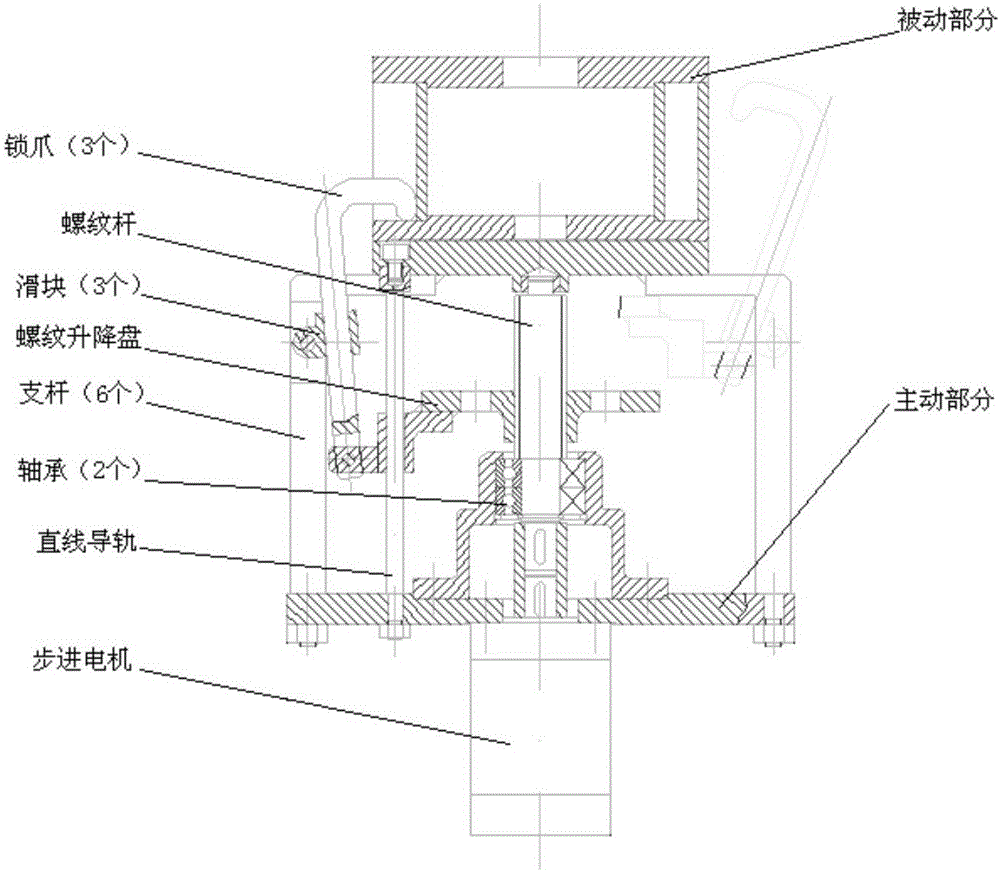
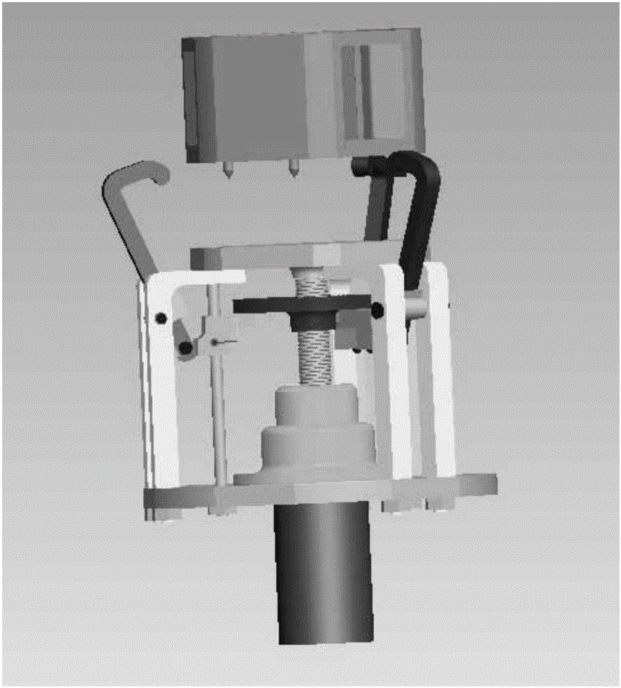
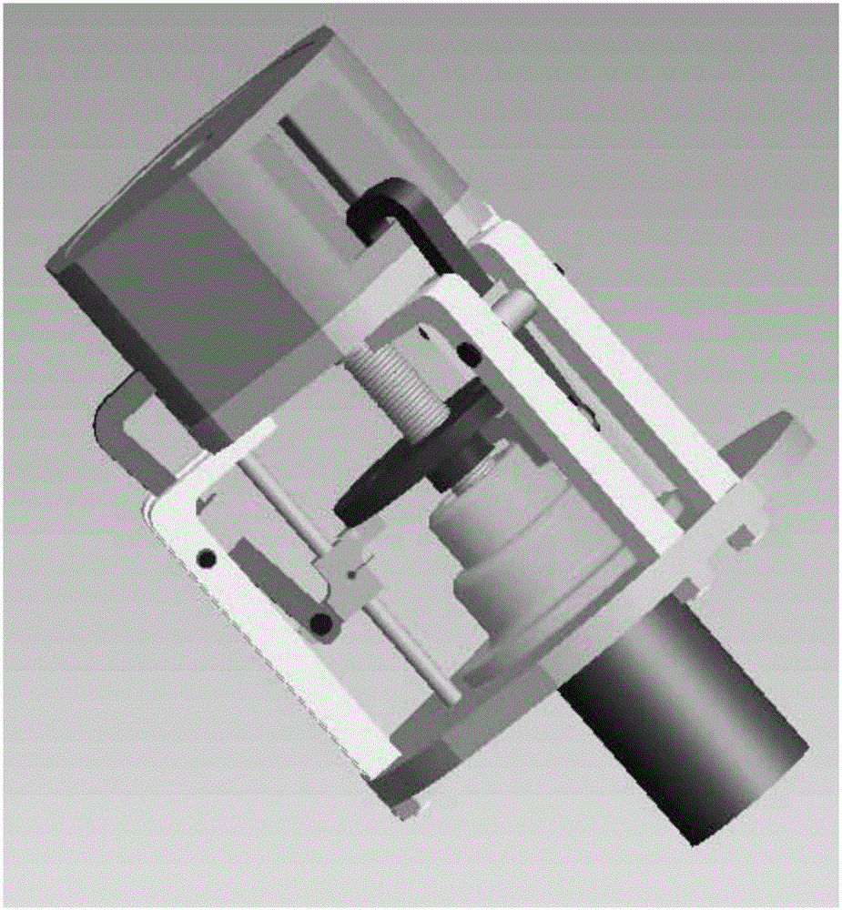
[0081] Among them, the three-finger grasping mechanism consists of two parts, the active part and the passive part, such as figure 1 As shown, the active part is installed at the end of the robotic arm of the service spacecraft as the end effector, and the passive part is installed on the replaceable module of the faulty satellite as a matcher of the robotic arm; the grasping process is shown in Figure 2(a) and Figure 2(b ); the three fingers in the three-finger grasping mechanism include No. 1 finger, No. 2 finger and No. 3 finger; No. 1 finger ...

specific Embodiment approach 2

[0127] Specific implementation mode two: the difference between this implementation mode and specific implementation mode one is: the specific steps of establishing a mathematical model according to the three-dimensional model described in step one are:

[0128] Step 11. Determine the size of the matching device mathematical model and the definition of the coordinate system, such as image 3 shown;

[0129] Step 12: Determine that the origin of the matcher coordinate system is at the geometric center of the matcher, that is, the center of mass. In the matcher coordinate system, the positive direction of the x-axis points to the apex of the No. 1 V-shaped groove, and the z-axis is perpendicular to the bottom surface of the No. 1 V-shaped groove. The y-axis forms a right-handed system;

[0130] Step 13, respectively determine the size, configuration and number of the three V-shaped grooves, the size, configuration and number of the matcher, and the distribution of the V-shaped ...

specific Embodiment approach 3

[0135] Embodiment 3: The difference between this embodiment and Embodiment 1 or 2 is that: the collision detection between the three fingers and the three V-shaped grooves in step 2 obtains the collision model of the three fingers and the three V-shaped grooves as follows: :

[0136] (1) Determine the position vectors of the three fingers in the inertial system respectively:

[0137] The position vectors of the three fingers in the inertial coordinate system are obtained by the end pose of the robot arm of the service spacecraft, the radius of the grasping domain, and the height of the tip of the three fingers from the inertial coordinate system at each moment during the grasping process, and the number 1 finger is taken as E.g Figure 5 shown;

[0138] The position of the grasping domain center of finger l in the inertial coordinate system is:

[0139]

[0140] in, is the description of the position vector of the end platform in the inertial system, is the descripti...


PUM


Abstract

The invention relates to a collision prediction method for a three-figure grasper and provides a collision prediction method for a three-figure grasper of a space robot to solve the problem that a method for predicting a collision when the space robot performs grasping operation in orbit is low in efficiency. The collision prediction method is implemented through the following steps: 1, designing a three-dimensional model of a three-figure grasping mechanism of the space robot, and building a mathematical model according to the three-dimensional model; 2, performing collision detection of the three-figure grasping mechanism according to the three-dimensional model and the mathematical model which are built in Step 1 to obtain a collision model, and calculating a collision force according to intrusion of the collision model; and 3, building a kinetic model of the three-figure grasping mechanism of the space robot by using the collision model and a mechanical arm system model, and designing a control system model of the three-figure grasping mechanism of the space robot according to the kinetic model of the three-figure grasping mechanism. The collision prediction method is applied to the field of three-figure grasper collision prediction.

Description

technical field [0001] The invention relates to a collision prediction method for a three-finger gripper, in particular to a collision prediction method for a three-finger gripper of a space robot. Background technique [0002] .With the continuous development of on-orbit service technology, when small spacecraft such as satellites fail in orbit, they can be repaired on-orbit by launching service spacecraft. After the service spacecraft enters orbit, it will rendezvous and dock with the faulty satellite. The space manipulator carried on it will grab the faulty module on the satellite and pull it out of the interface box, and then insert a new module to complete the repair task. Therefore, when designing the satellite, each functional module should use a unified adapter, and the corresponding actuator should be installed at the end of the manipulator to realize the rapid grabbing of the module by the manipulator. The matching device and the actuator are matched to form a gra...

Claims


Application Information

Patent Timeline
Patent Type & Authority Applications(China)
IPC IPC(8): B25J9/16
CPCB25J9/1602B25J9/1676
Inventor 魏承刘天喜汤亮张海博陈子坤
Owner HARBIN INST OF TECH
Why Eureka
Try Eureka