Steel plate cutting device

A cutting device, steel plate technology, applied in auxiliary devices, welding/cutting auxiliary equipment, auxiliary welding equipment, etc., can solve the problems of the bottom support plate being damaged, not having a good cutting support platform, and the cutting equipment being inconvenient to move, etc. High efficiency, flexible and convenient cutting and walking effect

Inactive Publication Date: 2020-06-02
HUANGSHI ONTIME ELECTROMECHANICAL
View PDF0 Cites 0 Cited by
  • Summary
  • Abstract
  • Description
  • Claims
  • Application Information

AI Technical Summary

Problems solved by technology

[0002] When cutting steel plates, most of them are carried out in the form of thermal cutting, but the existing cutting equipment is inconvenient to move, and at the same time there is no good cutting support platform, it is easy to destroy the bottom support plate during cutting

Method used


Image

  • Steel plate cutting device

Examples


Embodiment Construction

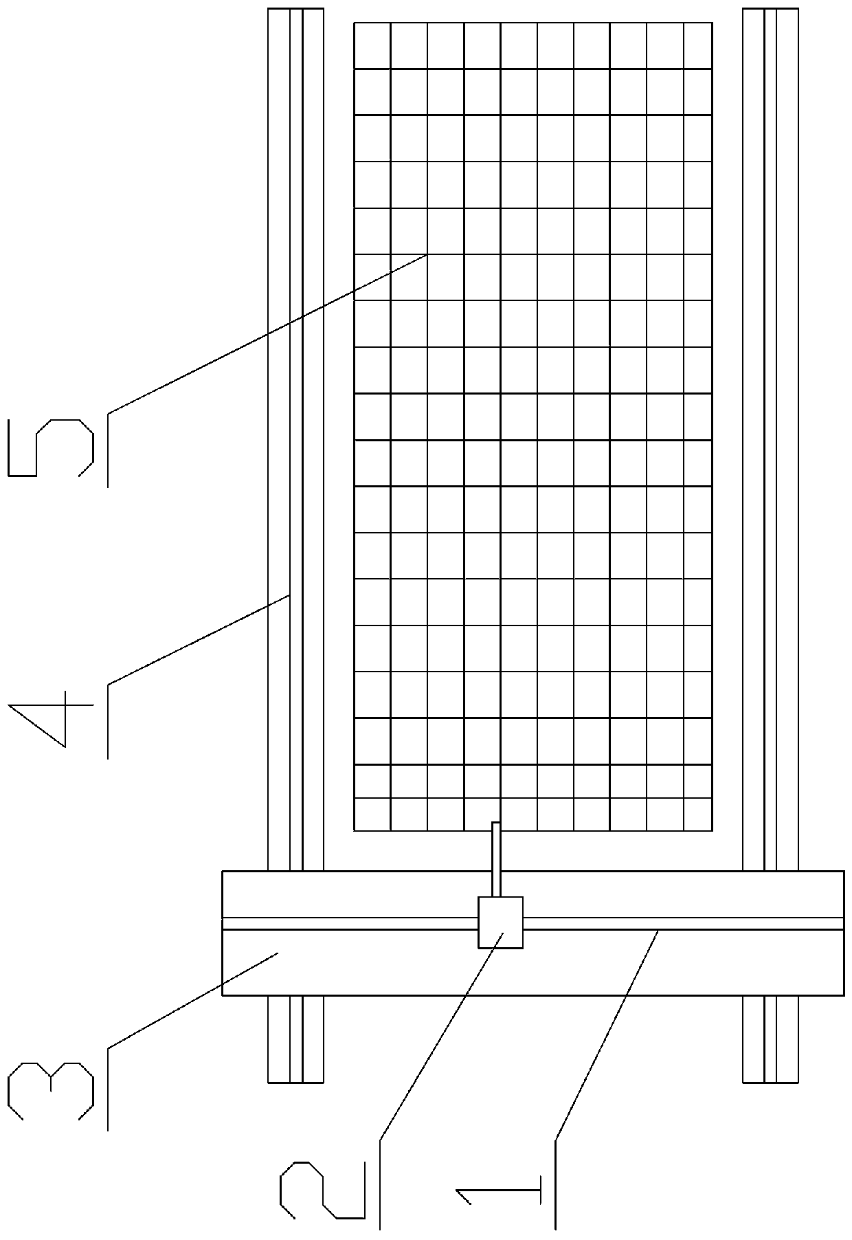
[0008] see figure 1 , the present invention is a steel plate cutting device, which has a grid shelf 5, a transverse rail 4 is respectively installed on both sides of the grid shelf, a crane 3 is horizontally erected on the rail, the two sides of the truck walk on the track, and the top of the truck is A longitudinal track 1 is provided, on which a cutting machine 2 slides.

[0009] The equipment of the present invention is flexible and convenient for cutting and walking, has high efficiency, and at the same time protects the supporting bottom plate in place.


PUM


Abstract

The invention relates to a steel plate cutting device. The steel plate cutting device is provided with a grid shelf, the two sides of the grid shelf are each provided with a transverse rail, a traveling crane is transversely erected on the rails, the two sides of the traveling crane walk on the rails, a longitudinal rail is arranged at the top of the traveling crane, and a cutting machine is slidably installed on the longitudinal rail. The steel plate cutting device has the advantages of flexible and convenient cutting and walking, high efficiency and being capable of protecting a supporting bottom plate in place.

Description

technical field [0001] The invention relates to the technical field of cutting equipment, in particular to a steel plate cutting device. Background technique [0002] When cutting steel plates, many of them are carried out in the form of thermal cutting, but the existing cutting equipment is inconvenient to move, and at the same time there is no good cutting support platform, and the bottom support plate is easy to be damaged during cutting. Contents of the invention [0003] The object of the present invention is to provide a steel plate cutting device for the above-mentioned problems existing in the traditional steel plate cutting equipment. [0004] The specific solution of the present invention is: a steel plate cutting device, with a grid shelf, a transverse rail is installed on both sides of the grid shelf, a crane is horizontally erected on the track, the two sides of the truck walk on the track, and the top of the truck There is a longitudinal track on which a cut...

Claims


Application Information

Patent Timeline
Patent Type & Authority Applications(China)
IPC IPC(8): B23K37/02
CPCB23K37/0229
Inventor 方向明王斌
Owner HUANGSHI ONTIME ELECTROMECHANICAL
Why Eureka
Try Eureka