Sharp surgical instrument transfer bending plate

A technique for surgical instruments and curved discs, which is applied to the field of surgical instrument transmission curved discs, can solve the problems of lack of fixation, easy slippage of instruments, and falling of instruments, and achieves the effects of in place protection and strong practicability.

Pending Publication Date: 2018-11-30
NANNING SECOND PEOPLES HOSPITAL
View PDF0 Cites 0 Cited by
  • Summary
  • Abstract
  • Description
  • Claims
  • Application Information

AI Technical Summary

Problems solved by technology

[0003] In recent years, many hospitals have been promoting the use of curved discs to transfer sharp surgical instruments, but the effect is not good in practical applications. The main reason is that the structural design of conventional instrument transfer curved discs is not reasonable enough, and there are the following defects:
[0004] (1) When using a conventional instrument to transfer flat sharp instruments such as a scalpel on a curved plate, since the instrument is placed flat on the bottom of the curved plate and is not fixed, it is difficult for the surgeon to grasp it stably, and the instrument is easy to slip. Shen is vulnerable to blade cuts
[0005] (2) When using a conventional instrument to transfer the curved plate to transfer the needle-holding forceps holding the suture needle, because the tip of the suture needle is exposed and the needle-holding forceps cannot be fixed, the surgeon is vulnerable to being stabbed by the suture needle when grasping
[0006] (3) Since there is no suitable handle for the conventional instrument transmission bending disc, it is not easy for nurses to hold the bending disc firmly, and it is easy to cause the bending disc to slip off and the instrument to fall.

Method used


Image

  • Sharp surgical instrument transfer bending plate
  • Sharp surgical instrument transfer bending plate
  • Sharp surgical instrument transfer bending plate

Examples


Embodiment Construction

[0026] The present invention will be further described below in conjunction with the accompanying drawings.

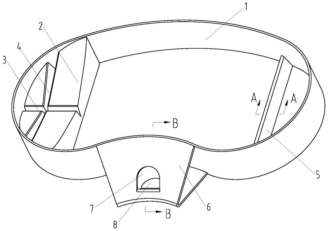
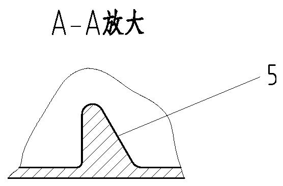
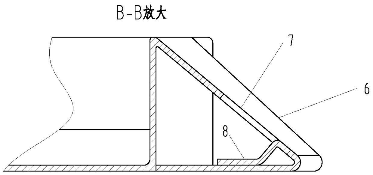
[0027] Such as Figure 1-6 As shown, the main body of the sharp surgical instrument transmission bending disc is a pig waist-shaped disc body 1, and a bracket 2 is provided inside the disc body 1 at the left end in the direction of its long axis, and the bracket 2 is fixedly mounted on the bottom of the disc and held The left end of the frame 2 extends to the plate wall at the left end of the plate body 1. The top surface of the bracket 2 is in the shape of a valley with a low middle and high sides in the longitudinal section. There is also a longitudinal V-shaped groove 4 on the top surface of the bracket 2. The horizontal V-shaped groove 3 and the longitudinal V-shaped groove 4 form a cross arrangement; The retaining bar 5, the retaining bar 5 is fixedly erected on the bottom of the pan and the two ends of the retaining bar 5 extend to the disc wall, the height of t...


PUM


Abstract

The invention provides a sharp surgical instrument transfer bending plate. The main body is a pig-waist-shape plate body; a carriage is installed at a left end, in the long axis direction, inside theplate body; a top surface of the carriage is valley-shaped and is provided with a transverse V-shaped groove and a vertical V-shaped groove which are in cross arrangement; a vertical block bar is installed at a right end, in the long axis direction, inside the plate body; a reverse flanging handle is installed outside the plate body; a reverse flanging inclined plane of the reverse flanging handleis provided with a finger jack. When the bending plate is used for transferring scalpels and clamping surgical instrument such as needle holders with seamed needles, the sharp parts of the surgical instrument can be effectively shielded and the surgical instrument can be fixed and maintained easy to take. When the bending plate is held by a hand for transferring, the bending plate can be held with palms and fingers can insert into the finger jack to prevent the bending plate from slipping off from the hand. Therefore, when the bending plate is used for transferring sharp surgical instrument,medical staff can be protected properly and the bending plate is practical and suitable for clinical promotion application.

Description

technical field [0001] The invention relates to a surgical instrument transmission bending plate, in particular to a bending plate used by medical staff to transmit sharp surgical instruments during surgical operations, and belongs to the technical field of medical auxiliary instruments. Background technique [0002] Medical staff will face severe occupational exposure risks when performing surgical operations. Sharp instrument injuries are the main occupational factors leading to blood-borne disease infections. Passing sharp instruments during surgical operations is a high-risk link of occupational exposure. Hands-free technique (HFT) is currently recommended as the best way to reduce sharps injuries and blood-borne diseases in the operating room. The core requirement of using hands-free technology to pass sharps is that two people cannot touch the sharps at the same time when passing the sharps. Instrument transmission, that is, the nurse indirectly transmits sharp surgic...

Claims


Application Information

Patent Timeline
Patent Type & Authority Applications(China)
IPC IPC(8): A61B50/33
CPCA61B50/33A61B50/3001
Inventor 莫丽平谭云燕黄华庚汪莉杨秀媛李婧肖友罗冬兰李捷琼吕廉威何秀丽黄秋溪韦佳盈
Owner NANNING SECOND PEOPLES HOSPITAL
Why Eureka
Try Eureka