Eureka AIR delivers breakthrough ideas for toughest innovation challenges, trusted by R&D personnel around the world.

Plate edge searching method of laser cutting machine, calibration system and edge searching system

A laser cutting machine and sheet material technology, applied in laser welding equipment, welding equipment, metal processing equipment, etc., can solve the problems of low universality, low efficiency, and low edge-seeking efficiency, and achieve improved cutting accuracy and flexible installation and disassembly , The effect of improving cutting efficiency

Active Publication Date: 2021-12-24
JINAN BODOR LASER CO LTD
View PDF9 Cites 0 Cited by
  • Summary
  • Abstract
  • Description
  • Claims
  • Application Information

AI Technical Summary

Problems solved by technology

[0003] When adopting the capacitive edge-finding method, if the plate has a large format, the laser head needs to move a long distance to complete the edge-finding process, which takes a long time and has low edge-finding efficiency
Moreover, if the size of the plate is set incorrectly, the inclination of the plate is too large, or the initial position of the laser head is selected improperly, mechanical damage may be caused, and there are certain safety hazards; the existing visual edge finding methods mainly use template matching, based on template matching The universality of the method is low, and the feature matching points need to be manually set for each plate of different thickness and material, and it takes a lot of time to perform the calibration test, and the efficiency is low

Method used

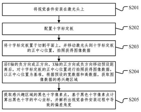
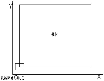
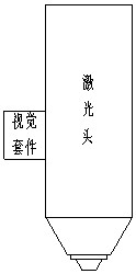

Image

  • Plate edge searching method of laser cutting machine, calibration system and edge searching system
  • Plate edge searching method of laser cutting machine, calibration system and edge searching system
  • Plate edge searching method of laser cutting machine, calibration system and edge searching system

Examples


Embodiment Construction

[0085] The following will clearly and completely describe the technical solutions in the embodiments of the present invention with reference to the accompanying drawings in the embodiments of the present invention. Obviously, the described embodiments are only some, not all, embodiments of the present invention. Based on the embodiments of the present invention, all other embodiments obtained by persons of ordinary skill in the art without making creative efforts belong to the protection scope of the present invention.

[0086] Those of ordinary skill in the art can realize that the units and algorithm steps of each example described in the embodiments disclosed in the method and system for edge finding of a laser cutting machine provided by the present invention can be implemented with electronic hardware, computer software, or both. In order to clearly illustrate the interchangeability of hardware and software, the composition and steps of each example have been generally des...


PUM


Abstract

The invention provides a plate edge searching method and system of a laser cutting machine, and relates to the technical field of laser cutting. The plate edge searching method is divided into a camera calibration part and a plate edge searching part. A camera, a light source and a protective cover are integrated; distortion correction is carried out on the camera; a visual kit is installed at a proper position of a laser head; automatic calibration is carried out, and the coordinate difference between the laser head and the camera, the tiny deviation angle caused in the camera installation process and the proportionality coefficient of the real world and the pixel world can be obtained through calibration; the laser head is moved to a mechanical origin position, picture taking is conducted, a rough coordinate of an angular point of a plate is calculated, and the camera view center is moved to a coordinate position; picture taking is conducted, the accurate coordinate of the angular point of the plate and the inclination angle of the plate are calculated, and the laser head is moved to the position over the angular point of the plate; and the edge searching precision is verified through a frame, the cutting precision is improved, the position corresponding to the laser head is arranged according to actual needs, the occupied space is smaller, mounting and dismounting are flexible, and protection is in place.

Description

technical field [0001] The invention relates to the technical field of laser cutting, in particular to a plate edge-finding method, a calibration system and an edge-finding system for a laser cutting machine. Background technique [0002] Laser cutting machines have ushered in rapid development due to their high precision and high efficiency. Usually, the laser cutting machine needs to perform edge-finding operation before cutting metal sheets. At present, there are mainly two edge-finding methods: one is the edge-finding method based on capacitance, and the other is the edge-finding method based on vision. [0003] When adopting the capacitive edge-finding method, if the plate has a large format, the laser head needs to be moved a long distance to complete the edge-finding process, which takes a long time and has low edge-finding efficiency. Moreover, if the size of the plate is set incorrectly, the inclination of the plate is too large, or the initial position of the lase...

Claims


Application Information

Patent Timeline
Patent Type & Authority Applications(China)
IPC IPC(8): B23K26/70B23K26/38
CPCB23K26/702B23K26/38
Inventor 杨绪广石立王爽彭利张浩于飞
Owner JINAN BODOR LASER CO LTD
Why Eureka
Eureka Blog
Learn More