
Cloth slitter
A strip cutting machine and cloth technology, applied in the cutting of textile materials, textiles and papermaking, metal processing, etc., can solve the problems of low automation, slow moving speed, low work efficiency, etc., achieve high-precision fast cutting, prevent bluntness The effect of chemicalization and high cutting precision
- Summary
- Abstract
- Description
- Claims
- Application Information
AI Technical Summary
Problems solved by technology
Method used
Image

Examples
Embodiment Construction
[0017] The preferred embodiments of the present invention will be described in further detail in conjunction with the accompanying drawings.
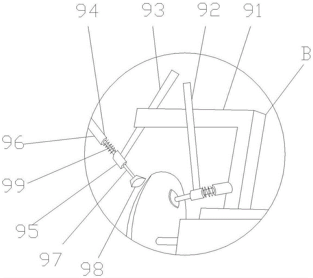
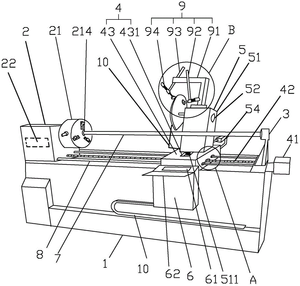
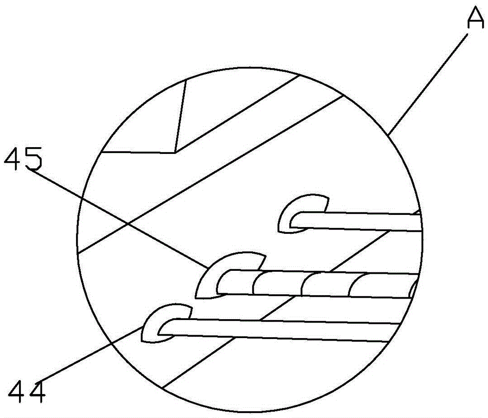
[0018] Such as Figure 1-5 Described a kind of cloth cutting machine, comprises frame 1, machine head 2, machine tail 3, moving device 4, cutting device 5, sharpening device 9 and PLC control box 6, described machine head 2 and machine tail 3 Located on both sides of the bit frame 1 respectively, the machine head 2 includes a clamping chuck 21 and a driver 22 that drives the clamping chuck 21 to rotate, and one end of the sleeve rod 7 is fixedly connected with the clamping chuck 21, and the sleeve The other end of the rod 7 is connected with the tail 3. The clamping chuck 21 is a cylindrical structure, and the clamping chuck 21 includes a draw groove 211, a movable claw 212 and a pushing mechanism 213, and the center of one side of the clamping chuck 21 is provided with a sleeve rod 7 The connecting mounting hole 214, the clamping chu...
PUM
 Abstract
Description
Claims
Application Information