vertical granulator

A granulator and granulation technology, which is applied in the field of manufacturing equipment, can solve the problems of unsightly appearance of the product, reduce the precision of granulation, and affect the quality of the product, and achieve the effect of improving the appearance, sharpness, and appearance

Inactive Publication Date: 2018-07-24
DONGGUAN BOZHAN MACHINERY SCI & TECH CO LTD
View PDF7 Cites 0 Cited by
  • Summary
  • Abstract
  • Description
  • Claims
  • Application Information

AI Technical Summary

Problems solved by technology

[0004] On the one hand, the blade is a hob, and the cutting direction of the blade forms an acute angle with the conveying direction of the material strip. The movement of the blade is arc-shaped, and the rolling cutting principle is adopted to cut the material strip into granular products. The cut surface of the product is an arc-shaped cut surface. It is an inner arc, and the other side is an outer arc, which makes the appearance of the product not beautiful, and the inner arc tip of the cut surface is easy to crack, resulting in a short service life of the product
In the second aspect, the hob often breaks during use, and the blade and the cutter shaft are an integrated hob. There are multiple blades and cutter shafts on one hob, and any blade can no longer be used after chipping. The entire hob needs to be replaced, otherwise the product quality will be affected; if any part of the large blade with separate blade and cutter shaft is chipped, the entire large blade needs to be replaced, otherwise the product quality will also be affected and the cutting accuracy will be reduced

Method used


Image

  • vertical granulator
  • vertical granulator
  • vertical granulator

Examples


Embodiment Construction

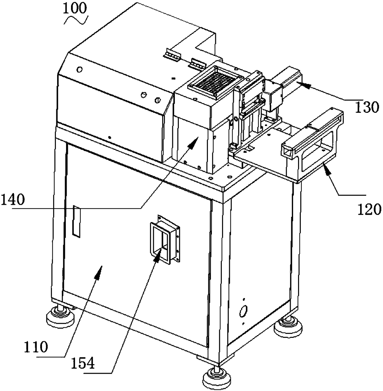
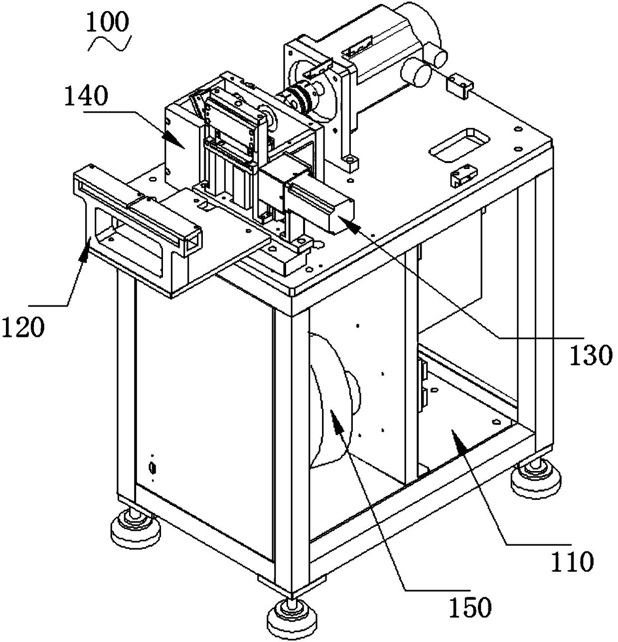
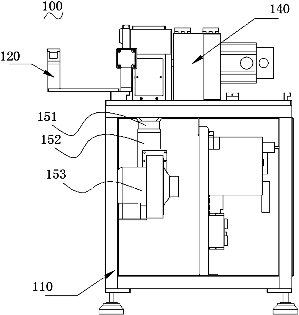
[0039] like Figure 1 ~ Figure 3 Shown are respectively a perspective view, an expanded perspective view and a front view of the present invention.

[0040] The vertical granulator 100 comprises a frame 110 which is hollow inside, a filter mechanism 120 installed above the frame 110, a wire delivery mechanism 130, a granulator 140 and a discharge mechanism 150 installed inside the frame 110; The filter mechanism 120 is located on the side above the frame 110, and is used to filter the nylon thread. The nylon wire is transported from the filter mechanism 120 to the pelletizing mechanism 140, and the pelletizing mechanism 140 is used to cut the nylon wire into nylon sand. Outward output.

[0041] like Figure 4 ~ Figure 6 As shown, they are respectively a perspective view, an expanded perspective view and another perspective view of the pelletizing mechanism of the present invention.

[0042] The pelletizing mechanism 140 includes a flying knife 144 for cutting, and also inc...


PUM


Abstract

The invention relates to the field of manufacturing equipment, in particular to a vertical granulator. The vertical granulator comprises a fly cutter used for conducting cutting. The fly cutter comprises a flat and straight installing part, a cutter body obliquely arranged on the side edge of the installing part, and a blade arranged at the bottom of the cutter body. The lower end face of the cutter body is located below the lower end face of the installing part. The installing part, the cutter body and the blade are integrally formed. The plane where the blade is located is perpendicular to the plane where the cutter body is located. A first included angle is formed by the face, close to the outer side, of the cutter body and the face where the blade is located. A second included angle is formed by the face, close to the inner side, of the cutter body and the face where the blade is located. The first included angle ranges from 8 degrees to 12 degrees, and the second included angle ranges from 25 degrees to 35 degrees. According to the vertical granulator, the fly cutter circumferentially moving is adopted, the fly cutter is perpendicular to the material strip conveying direction, and a product obtained through cutting is attractive in appearance and free of inner arc tip, long in service life and high in cutting precision.

Description

technical field [0001] The invention relates to the field of manufacturing equipment, in particular to a vertical granulator. Background technique [0002] Nylon sand is made of polyamide fiber (POLYAMIDE), and its shape is translucent milky white crystalline thermoplastic polymer particles. Due to its certain toughness, non-machining, and no damage to the product to be processed during use, etc. , Widely used in sandblasting and shot blasting equipment. [0003] Nylon sand is a granular product formed after nylon thread is granulated by a special granulator. In the granulator of the prior art, the purpose of granulation is achieved by continuously rolling and shearing granular or strip-shaped plastics through the hob. The performance of the hob is one of the key factors to ensure whether the granulator can produce normal slices. . At present, among the pelletizer hobs that appear on the market, some blades and the cutter shaft are designed in one piece, and some blades a...

Claims


Application Information

Patent Timeline
Patent Type & Authority Patents(China)
IPC IPC(8): B29B9/00B26D1/29B26D7/01B26D7/18B26D7/26B29K77/00
CPCB26D1/0006B26D1/29B26D7/01B26D7/1863B26D7/2614B26D2001/0033B26D2001/006B26D2001/0066B29B9/00B29K2077/00
Inventor 张学志
Owner DONGGUAN BOZHAN MACHINERY SCI & TECH CO LTD
Why Eureka
Try Eureka