
A light guide column laser splitter

A light guide column and splitter technology, applied in laser welding equipment, metal processing equipment, welding equipment, etc., can solve problems such as high end surface roughness, fire hazards, and reduced production efficiency of light guide columns, achieving strong practicability, The effect of avoiding fire

Active Publication Date: 2021-04-30
四川恒格光电科技有限公司
View PDF14 Cites 0 Cited by
  • Summary
  • Abstract
  • Description
  • Claims
  • Application Information

AI Technical Summary

Problems solved by technology

[0003] The light guide column is usually formed by hot-melt extrusion. In order to increase the output of the light guide column, the length of the light guide column after hot-melt extrusion is generally longer, while the length of the conventionally used light guide column is shorter. Therefore, after the preparation is completed, it is necessary to Carry out the cutting of the light guide column, and the existing cutting device mostly adopts the way of knife cutting, although this cutting method can carry out the cutting of the light guide column, but will produce a large amount of debris in the cutting process, at the same time, in the cutting process, Due to the existence of debris, it is easy to cause a fire. At the same time, after the cutting is completed in this way, the end surface roughness is relatively high. After the cutting is completed, the end surface of the light guide column needs to be reprocessed, thereby reducing the production efficiency of the light guide column.

Method used


Image

  • A light guide column laser splitter
  • A light guide column laser splitter
  • A light guide column laser splitter

Examples


Embodiment Construction

[0036] In order to make the purpose, technical solutions and advantages of the embodiments of the present invention clearer, the technical solutions in the embodiments of the present invention will be clearly and completely described below in conjunction with the drawings in the embodiments of the present invention. Obviously, the described embodiments It is a part of embodiments of the present invention, but not all embodiments. The components of the embodiments of the invention generally described and illustrated in the figures herein may be arranged and designed in a variety of different configurations.

[0037] Accordingly, the following detailed description of the embodiments of the invention provided in the accompanying drawings is not intended to limit the scope of the claimed invention, but merely represents selected embodiments of the invention. Based on the embodiments of the present invention, all other embodiments obtained by persons of ordinary skill in the art wi...


PUM


Abstract

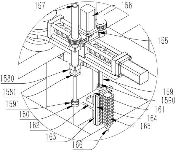
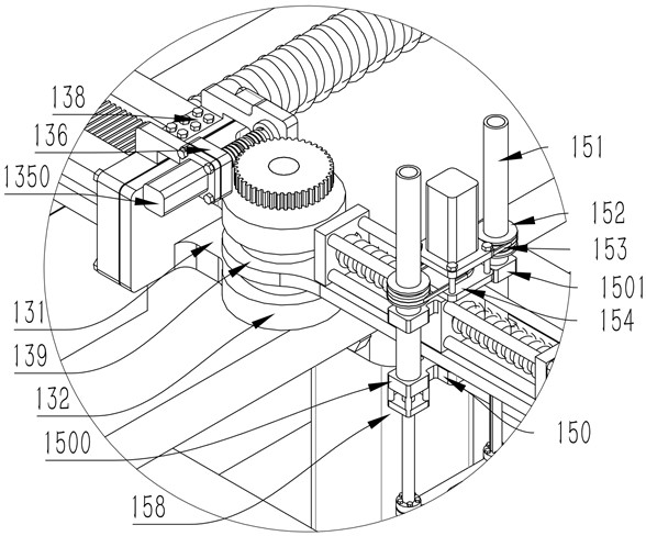
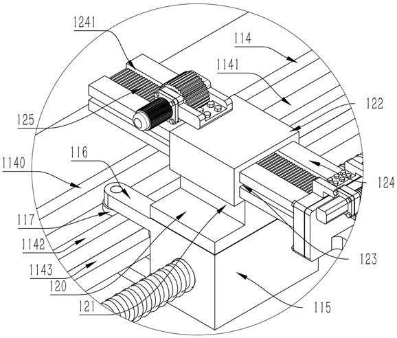
A light guide column laser slitting device, comprising: a cutting assembly, including a support member, the support member is provided with a pair of translation members, each translation member is provided with a telescopic member, and the telescopic member is provided with an angle adjustment member, and the angle adjustment member is provided with The lateral movement member is provided with a cutting member; the clamping assembly includes a pair of side frame members arranged on both sides of the support member, clamping members are provided at both ends of the side frame member, and the outer side of the side frame member is provided with Move support members. The invention adopts laser to cut the light guide column. During the cutting process, no debris will be generated, so as to avoid fire. During the cutting process, the cutting of multiple light guide columns can be completed. During the cutting process, both ends of the light guide columns can be clamped. During the cutting process, the local clamping and positioning of the light guide columns can be performed to prevent the bending of the light guide columns from affecting the cutting. precision.

Description

technical field [0001] The invention relates to the related technical field of lens processing equipment, in particular to a light guide column laser splitter. Background technique [0002] A light guide column is an optical device that transmits light from one light source to another point at a certain distance from the light source with minimal loss. The light is transmitted inside the light guide column by total internal reflection. The light guide column is usually made of optical materials. Such as acrylic resin, polycarbonate, epoxy resin and glass, the light guide rod can be used to transmit the light of the LED on the PCB to the product panel to display the relevant status, and can also gather and guide the light for the backlight of the LCD display. It can also be used to illuminate patterns on see-through windows. [0003] The light guide column is usually formed by hot-melt extrusion. In order to increase the output of the light guide column, the length of the li...

Claims


Application Information

Patent Timeline
Patent Type & Authority Patents(China)
IPC IPC(8): B23K26/38B23K26/402B23K26/70
CPCB23K26/38B23K26/402B23K26/702
Inventor 古锐杨斌何江赵光荣朱正国
Owner 四川恒格光电科技有限公司
Learn More