Portable electric cutting device with blower mechanism

A cutting device, portable technology, applied in the field of portable electric cutting devices, can solve the problems of reducing the visibility of marking lines, catheter obstruction, and reduced assembly efficiency

Active Publication Date: 2004-05-19
HITACHI KOKI CO LTD
View PDF1 Cites 22 Cited by
  • Summary
  • Abstract
  • Description
  • Claims
  • Application Information

AI Technical Summary

Problems solved by technology

[0009] However, when confirming the positional relationship between the marking line and the blade edge of the saw blade, the guide tube becomes an obstacle, which reduces the visibility of the marking line
In addition, due to the increase in the number of components, assembly efficiency decreases and costs increase

Method used


Image

  • Portable electric cutting device with blower mechanism
  • Portable electric cutting device with blower mechanism
  • Portable electric cutting device with blower mechanism

Examples


Embodiment Construction

[0070] Next, a portable electric circular saw according to an embodiment of the present invention will be described with reference to the drawings. First, refer to Figure 1-28 A portable electric circular saw according to a first embodiment of the present invention will be described.

[0071] (1) Basic structure

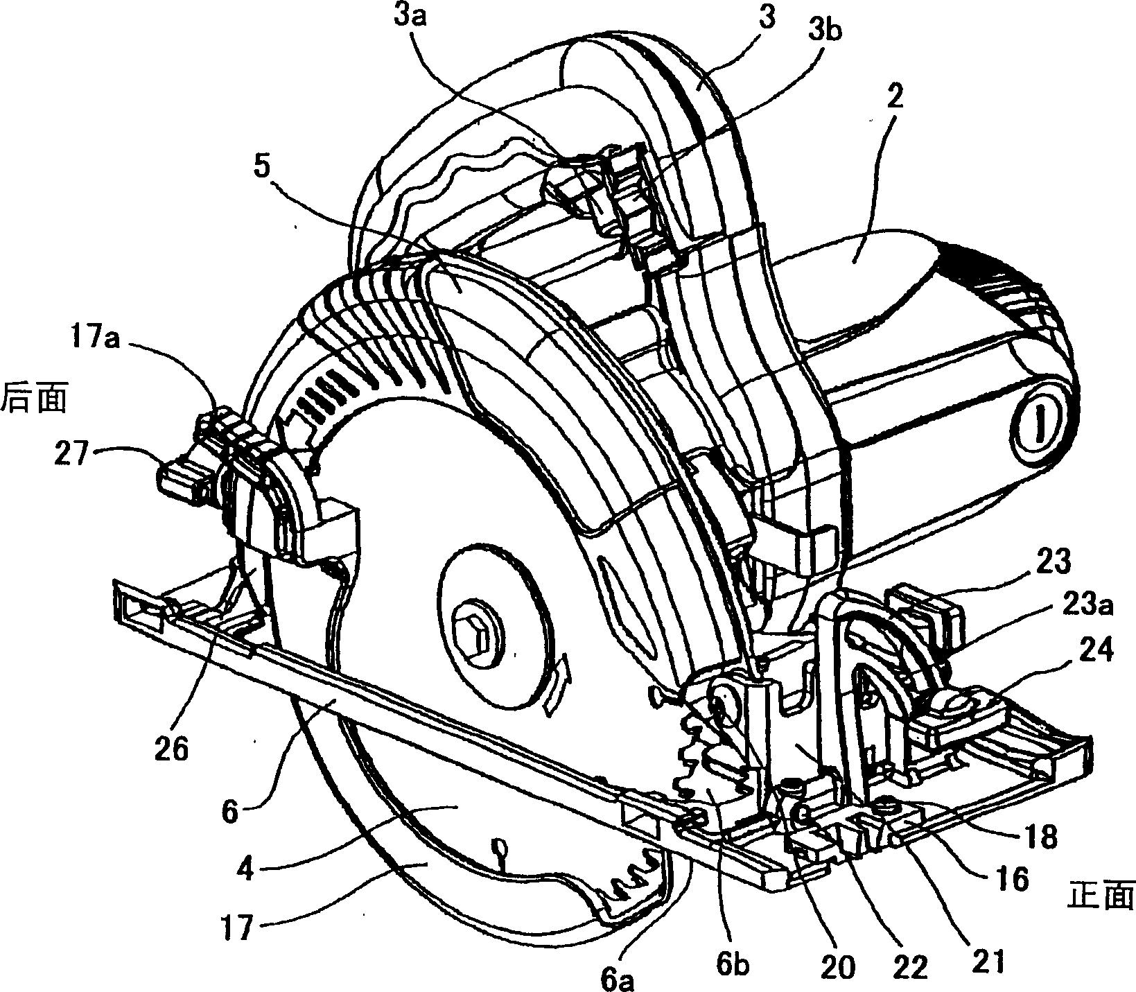
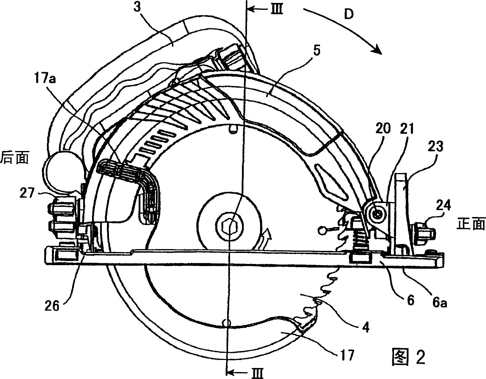
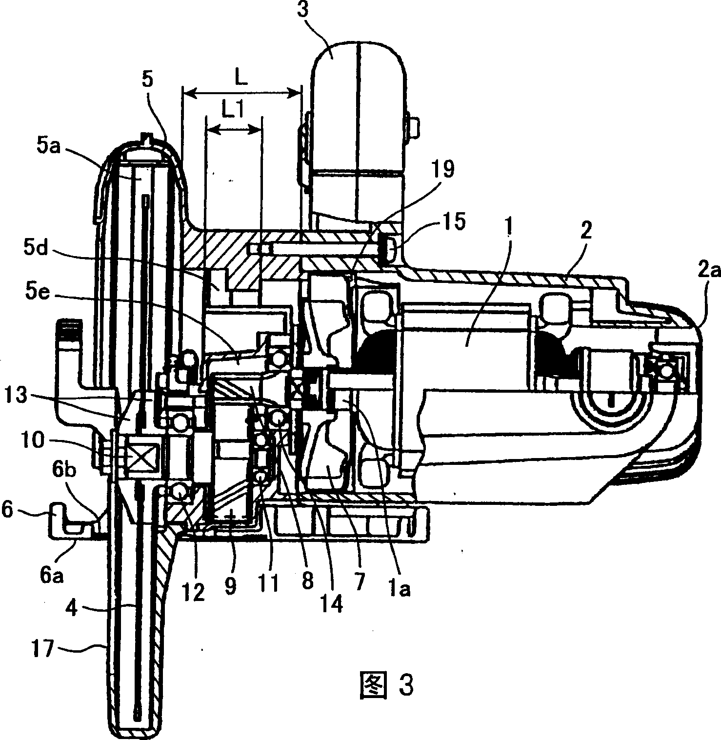
[0072] like figure 1 As shown in FIG. 3 , the portable electric circular saw in this embodiment includes a motor 1 , a casing 2 , a handle 3 , a saw blade 4 , a saw cover 5 , a bottom plate 6 , and a fan 7 . The motor 1 drives the saw blade 4 to rotate. The housing supports and accommodates the motor 1 . The handle 3 is integral with the housing 2 or connected to the housing 2 as a separate component. The user can turn on or off the motor 1 by manipulating the switch 3 a of the handle 3 . The saw cover 5 is connected to the housing 2 and has a saw blade housing part 5a. The saw blade 4 has a fan-side flank facing the fan 7 and a housing part-side flank facing...


PUM


Abstract

Fanned air generated by a fan to cool a motor is discharged from a housing through fanned air discharge ports toward an opening formed in a base. The fanned air discharged toward the opening is then introduced into a groove in fluid communication with the opening. The groove is formed in a bottom surface of the base and has an open side at a front side of the base. The fanned air is then discharged from the front side of the base, blowing off saw dust on a cutting object so as to prevent dust from accumulating on a marking line on the cutting object.

Description

technical field [0001] The present invention relates to portable electric cutting devices, and more particularly to portable electric cutting devices provided with an exhaust mechanism for exhausting air from the housing to the blade housing portion of the saw cover. Background technique [0002] When cutting an object to be cut (such as wood) by using a portable electric cutter (hereinafter referred to as a "portable electric circular saw"), in order to improve cutting accuracy, draw a marking line on the object to be cut, and then follow the The marked line is cut. More specifically, a guide vane for indicating an edge portion of the saw blade is disposed on the front end of the base plate so that the guide vane is located on an imaginary line extending toward a cutting direction of the saw blade. The user can cut the cutting object while directly confirming the positional relationship between the blade edge of the saw blade and the marking line on the cutting object. On...

Claims


Application Information

Patent Timeline
Patent Type & Authority Applications(China)
IPC IPC(8): B27G3/00B27B9/00
Inventor 吉田宪一郎谷本英之西河智雅高野晋二野中琢磨丹羽显司今井辉雄
Owner HITACHI KOKI CO LTD
Why Eureka
Try Eureka