Dismantling device of annular component in stepped hole

A technology for dismantling devices and stepped holes, which is applied in the field of dismantling devices for annular parts in stepped holes, which can solve the problems of stepped holes being damaged, difficult to disassemble, and low success rate, and achieve the effects of convenient operation, avoiding damage, and simple structure

Inactive Publication Date: 2020-06-02
淄博淄柴新能源有限公司
View PDF0 Cites 1 Cited by
  • Summary
  • Abstract
  • Description
  • Claims
  • Application Information

AI Technical Summary

Problems solved by technology

[0002] The stepped holes at the bottom of many mechanical structures are equipped with ring-shaped parts. The ring-shaped parts and the stepped holes generally adopt an interference fit, which is not easy to disassemble. They are generally wearing parts and need to be replaced frequently. If the existing technology is used to disassemble, the operation is cumbersome , the success rate is low, and the disassembly process is easy to cause damage to the stepped hole, which affects the repeated use of the stepped hole parts and causes waste

Method used


Image

  • Dismantling device of annular component in stepped hole
  • Dismantling device of annular component in stepped hole
  • Dismantling device of annular component in stepped hole

Examples


Embodiment

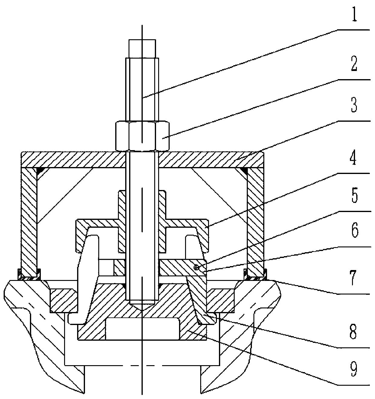
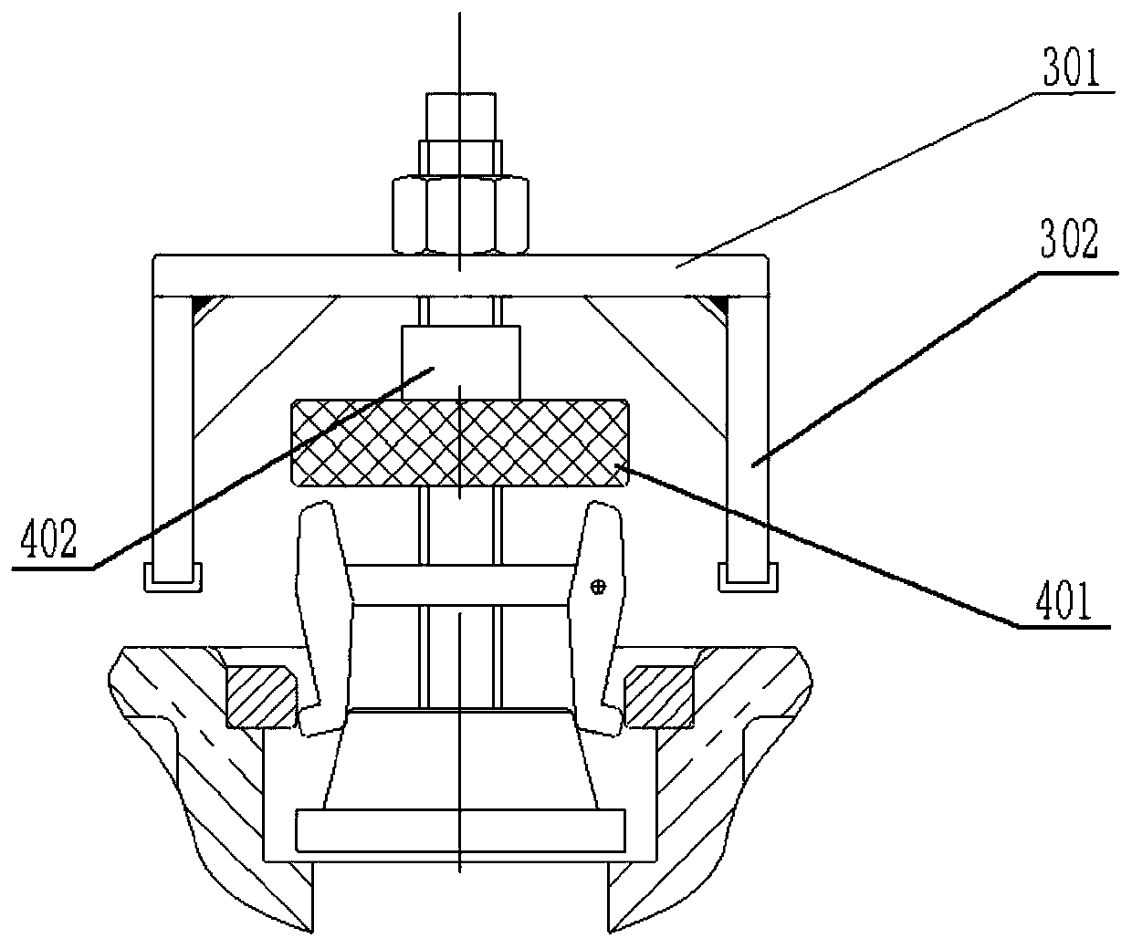
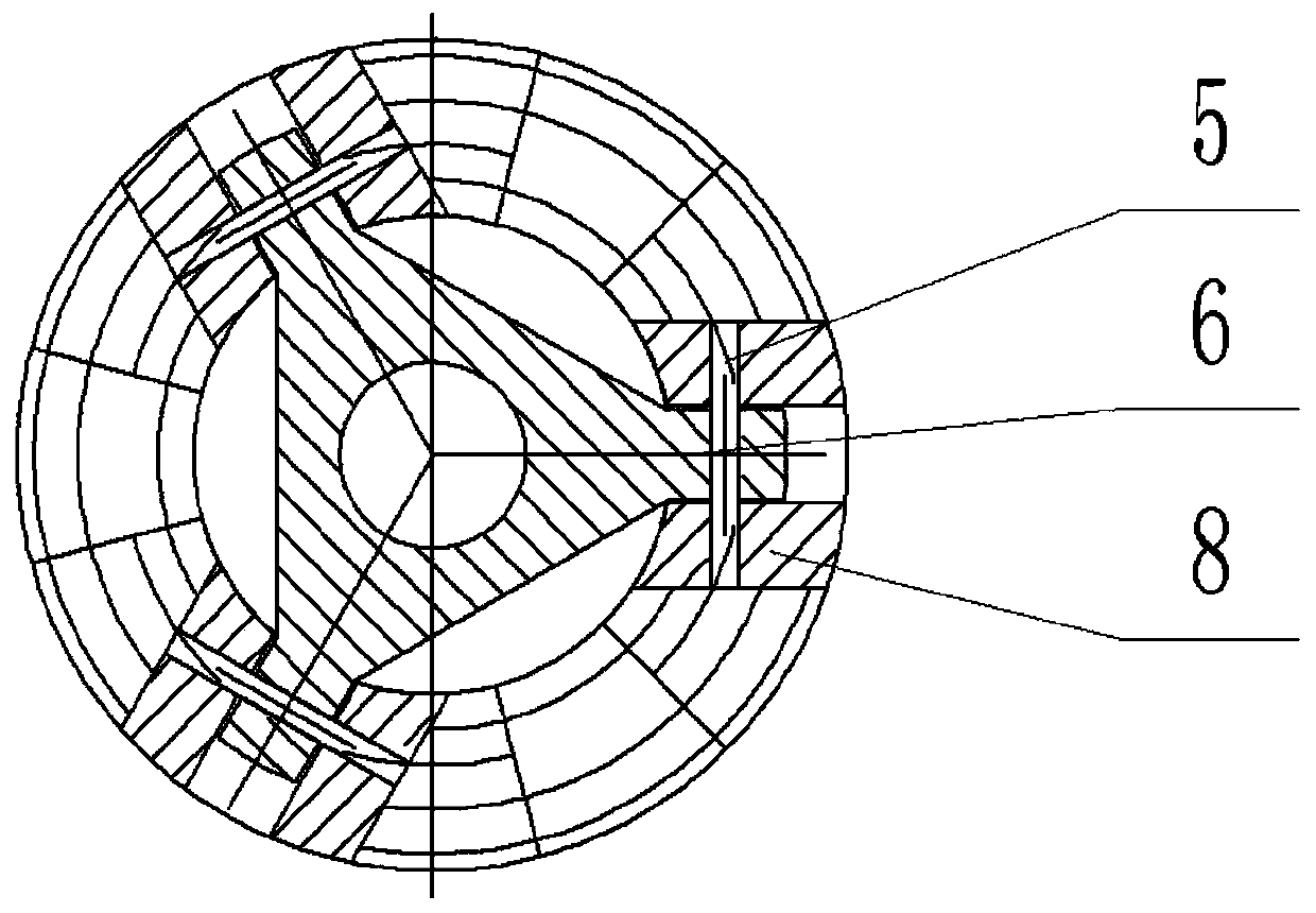
[0023] like Figure 1 to Figure 3 As shown, the dismantling device for the annular part in the stepped hole includes a screw rod 1, which passes through the support foot fixing plate 6, the support pressure seat 4, the support cover 3 and the lock nut 2 sequentially from bottom to top, and the support press Seat 4 and locking nut 2 are threadedly connected with screw rod 1, and support case 3 slides up and down along screw rod 1, and several braces 8 are arranged on the periphery of brace fixed disk 6, and the number of braces 8 is 3 in the present embodiment. The supporting leg 8 is connected in rotation with the supporting leg fixing plate 6, and the supporting base 4 includes a moving groove 401 capable of moving the top end of the supporting leg 8 to the screw rod 1, and the bottom end of the supporting leg 8 is provided with a protrusion facing away from the screw rod 1. A cylindrical pin 5 passing through the support leg 8 is provided on the periphery of the support leg ...


PUM


Abstract

The invention relates to the technical field of mechanical equipment, in particular to a dismantling device of an annular component in a stepped hole. The dismantling device comprises a screw rod, wherein the screw rod sequentially penetrates through an arm-brace fixing disc, a braced pressing seat, a support housing and a locking nut from top to bottom; a plurality of arm-braces are arranged on the circumference of the arm-brace fixing disc and are rotatably connected with the arm-brace fixing disc; the braced pressing seat comprises a movable groove enabling the top ends of the arm-braces tomove towards the screw rod; and a boss is arranged at the bottom end, back on to the screw rod, of each of the arm-braces. The dismantling device is convenient to dismantle and increases the reuse rate of the component in the stepped hole.

Description

technical field [0001] The invention relates to the technical field of mechanical equipment, in particular to a dismantling device for annular parts in stepped holes. Background technique [0002] The stepped holes at the bottom of many mechanical structures are equipped with ring-shaped parts. The ring-shaped parts and the stepped holes generally adopt an interference fit, which is not easy to disassemble. They are generally wearing parts and need to be replaced frequently. If the existing technology is used to disassemble, the operation is cumbersome , the success rate is low, and the disassembly process is easy to cause damage to the stepped hole, which affects the repeated use of the stepped hole parts and causes waste. Contents of the invention [0003] The technical problem to be solved by the present invention is to overcome the deficiencies of the prior art, and provide a device for dismantling the ring-shaped part in the stepped hole, which is convenient for disas...

Claims


Application Information

Patent Timeline
Patent Type & Authority Applications(China)
IPC IPC(8): B25B27/02
CPCB25B27/023
Inventor 梁杰辉李冬梅高绪伟董玉振王彬曲晨牛振国赵芳刘玉川李林
Owner 淄博淄柴新能源有限公司
Why Eureka
Try Eureka