Robot calibration method, robot calibration system and readable storage medium

A calibration method and a calibration system technology are applied in the field of robot calibration method, robot calibration system and readable storage medium, which can solve the problems of excessive data volume of the processor, complicated operation, high price, etc., so as to improve the trajectory accuracy and improve the usage. Accuracy, cost-effective solutions

CN111216138AInactive Publication Date: 2020-06-02JIHUA LAB
7 Cites 6 Cited by

Patent Information

Authority / Receiving Office
CN · China
Patent Type
Applications(China)
Current Assignee / Owner
Publication Date
2020-06-02
Estimated Expiration
Not applicable · inactive patent

Smart Images

  • Figure 1
    Figure 1
  • Figure 2
    Figure 2
Patent Text Reader

Abstract

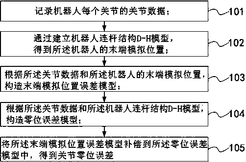
The invention discloses a robot calibration method, a robot calibration system and a readable storage medium. The robot calibration method comprises the following steps: recording the joint data of each joint of a robot; obtaining the tail end simulation position of the robot through establishing a robot connecting rod structure D-H model; constructing a tail end simulation position error model according to the joint data and the tail end simulation model of the robot; constructing a zero error model according to the joint data and the robot connecting rod structure D-H model; and compensatingthe tail end simulation position error model into the zero error model to obtain the joint zero error. According to the robot calibration method, the track precision of the robot can be improved on the premise of simple operation.
Need to check novelty before this filing date? Find Prior Art

Description

technical field

[0001] The invention relates to the technical field of robot calibration, in particular to a robot calibration method, a robot calibration system and a readable storage medium. Background technique

[0002] In the actual application process of the series articulated robot, if the zero position and / or tool coordinates of each or a certain joint are not accurate enough, it will cause a large deviation in the trajectory path at the end of the robot, which will affect the effect of the actual application.

[0003] The existing calibration method is generally to set high-precision equipment such as a laser tracker on the measuring equipment for calibration. This method is not only expensive, but also tends to cause hysteresis when the amount of data processed by the processor is too large. Although it can improve the trajectory accuracy of the robot, the operation is complicated and the cost is high. Contents of the invention

[0004] The main purpose of the pr...

Examples

Embodiment Construction

[0058] Exemplary embodiments of the present disclosure will be described in more detail below with reference to the accompanying drawings. Although exemplary embodiments of the present disclosure are shown in the drawings, it should be understood that the present disclosure may be embodied in various forms and should not be limited by the embodiments set forth herein. Rather, these embodiments are provided for more thorough understanding of the present disclosure and to fully convey the scope of the present disclosure to those skilled in the art.

[0059] The embodiment of the present application provides a robot calibration method, which can quickly realize the calibration of the robot joint zero position and the tool coordinate (the first measurement point), obtain the error between the actual robot joint zero position and the theoretical joint zero position, and then Error compensation into the controller will easily improve the trajectory accuracy of the robot, thereby imp...