A semi-automatic twist drill detection device

A detection device and twist drill technology, which is applied to measurement devices, mechanical measurement devices, and mechanical devices, etc., can solve the problems of difficulty in ensuring accuracy, not guaranteeing the length of the main cutting edge, affecting the life of the twist drill, etc., and achieves simple and convenient detection. Effect

Active Publication Date: 2021-06-18
CHANGZHOU INST OF MECHATRONIC TECH
View PDF18 Cites 0 Cited by
  • Summary
  • Abstract
  • Description
  • Claims
  • Application Information

AI Technical Summary

Problems solved by technology

[0002] Twist drill is a commonly used tool in machining, and it is also a kind of fragile tool. It needs repeated grinding during use. The quality of the drill directly affects the quality of drilling and drilling efficiency, and also affects the life of the twist drill. , In order to check whether the lengths of the two main cutting edges of the twist drill are equal and whether the angles of the two main cutting edges are equal during manual grinding, it is necessary to visually measure the length and angle of one main cutting edge from the front, and then visually measure the other main cutting edge after turning 180 degrees. The length and angle of the edge are compared repeatedly, because this comparison has time and space intervals, it is difficult to ensure the accuracy of this method, even if it is measured with a caliper, because there is no reliable card point, the measurement accuracy of the length of the main cutting edge also difficult to grasp
When grinding with a grinding machine, the ordinary grinding machine only ensures that the grinding angle is suitable, but does not guarantee that the lengths of the two main cutting edges are equal, and the slide plate needs to be moved manually

Method used


Image

  • A semi-automatic twist drill detection device
  • A semi-automatic twist drill detection device
  • A semi-automatic twist drill detection device

Examples


Embodiment Construction

[0024] The present invention will be described in further detail below in conjunction with the accompanying drawings and specific embodiments.

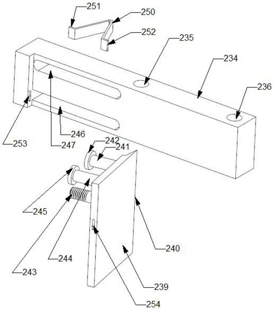
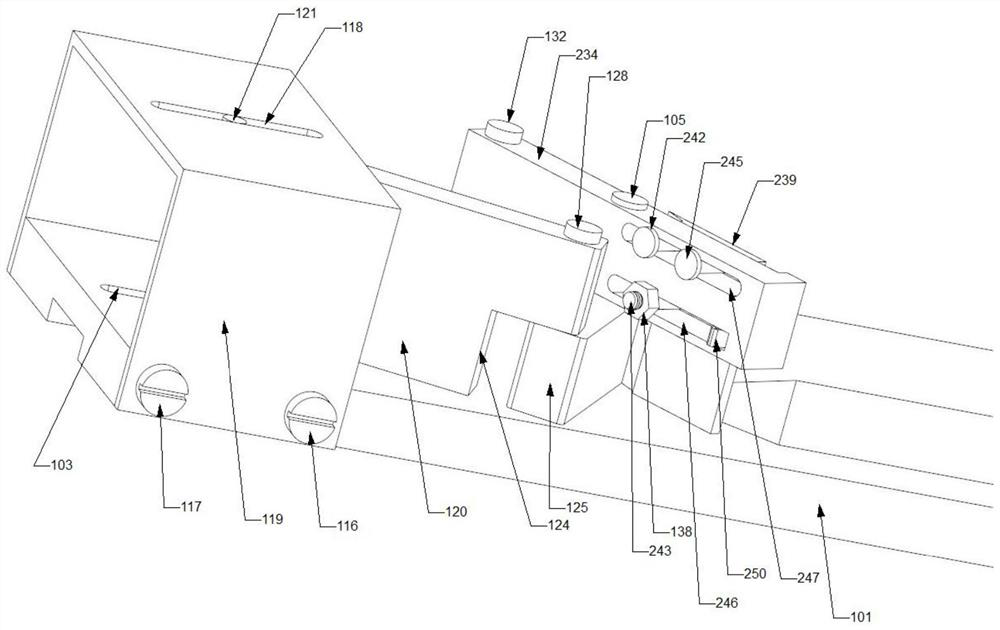
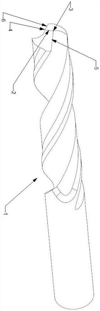
[0025] A semi-automatic twist drill detection device, comprising a main board 101, a V-shaped groove 102, a sliding groove 103 and a front rotating shaft 104;

[0026] Fixed V-shaped groove 102 is fixed on described main board 101, is used for placing measured twist drill 1, main board 101 front end has front rotating shaft 104, and front rotating shaft 104 is fixedly installed on main board 101, and is perpendicular to the upper surface of main board 101, and front rotating shaft There is a front shaft cap 105 at the top of 104, and there is a sliding groove 103 at the rear of the main board 101. The plane formed by the axis center of the front rotating shaft 104 and the center of the sliding groove 103 is the center plane of the detection device, which is recorded as the center plane, V-shaped groove 102 Symmetrical with respect to ...


PUM


Abstract

The invention belongs to the technical field of machining testing tools and relates to a semi-automatic twist drill testing device. The main board of the semi-automatic twist drill detection device is fixed with a V-shaped groove for placing the tested twist drill. The front end of the main board has a front shaft, which is fixedly installed on the main board and is perpendicular to the upper surface of the main board. The top of the front shaft has a The front shaft cap has a sliding groove at the rear of the main board. The plane formed by the axis of the front rotating shaft and the center of the sliding groove is the central plane of the detection device, which is recorded as the central plane. The V-shaped groove is symmetrical to the central plane, and the sliding groove is also Symmetrical about the central plane. It can be observed whether the angle of the two main cutting edges is consistent with the preset angle, and the length of the tested twist drill is not limited. The invention is simple, convenient and universal in detecting the twist drill, without worrying about the length of the twist drill to be tested, and can realize automatic sliding of the slide plate.

Description

technical field [0001] The invention belongs to the technical field of machining testing tools and relates to a semi-automatic twist drill testing device. Background technique [0002] Twist drill is a commonly used tool in machining, and it is also a kind of fragile tool. It needs repeated grinding during use. The quality of the drill directly affects the quality of drilling and drilling efficiency, and also affects the life of the twist drill. , In order to check whether the lengths of the two main cutting edges of the twist drill are equal and whether the angles of the two main cutting edges are equal during manual grinding, it is necessary to visually measure the length and angle of one main cutting edge from the front, and then visually measure the other main cutting edge after turning 180 degrees. The length and angle of the edge are compared repeatedly, because this comparison has time and space intervals, it is difficult to ensure the accuracy of this method, even if...

Claims


Application Information

Patent Timeline
Patent Type & Authority Patents(China)
IPC IPC(8): G01B5/02G01B5/24
CPCG01B5/02G01B5/24G01B5/243
Inventor 周斌虞文武蒋庆斌沈新阳莫莉萍钱金法
Owner CHANGZHOU INST OF MECHATRONIC TECH
Why Eureka
Try Eureka