Low-sight-distance vehicle safe driving control method

A driving control and line-of-sight technology, which is applied in the field of safe driving control of low-line-of-sight vehicles, and can solve problems such as congestion, shortening of the driver's line of sight, and traffic accidents.

Active Publication Date: 2020-06-05
中科美络科技股份有限公司
7 Cites 2 Cited by

AI-Extracted Technical Summary

Problems solved by technology

[0003] In the existing cases of traffic accidents, the traffic accidents caused by the driver's sight distance are particularly frequent. For example, due to the low visibility caused by heavy fog, rainy weather and other weather conditions, the driver's sight distance becomes shorter. Obstacles in the road environment such as ramps shorten the driver's sight distance, making it impossible to know the obstacles at a long distance in front of the vehicle, and it is easy to find obstacles too l...

Method used

In the embodiment of the present invention, according to the preset determination method, determining one of the preset vehicles in the target auxiliary sight range as the target auxiliary vehicle specifically includes: acquiring the target auxiliary sight range according to the first real-time road image The license plate is visible, and the vehicle whose license plate is completely visible is used as the preset vehicle; the visible viewing angle of the preset vehicle is calculated, and the preset vehicle with the largest visible viewing angle is used as the target auxiliary vehicle; the calculation method of the visible viewing angle is: the simulation camera is used as the starting point, Draw straight lines to the visible edge points on both sides of each preset vehicle, and take the angle between the two straight lines as the visible angle of view. By using the vehicle whose license plate is fully visible as the preset vehicle and the preset vehicle with the largest visible angle as the target auxiliary vehicle, the driver can more easily find the target auxiliary vehicle while the vehicle is driving.
It should be noted that, in the embodiment of the present invention, after the target auxiliary vehicle is determined, the visibility of the target auxiliary vehicle within the target auxiliary sight range is monitored in real time, and when it is not visible, steps S1 to S3 are re-executed to determine the vehicle Ahead Target Assist New target assist vehicles within sight range. By using the visibility of the target auxiliary vehicle as the selection condition, it can ensure that the driver of the own vehicle can see the target auxiliary vehicle in the real line of sight and the real-time display mod...

Abstract

The invention discloses a low-sight-distance vehicle safe driving control method, which comprises the following steps: acquiring a first real-time road image in front of a vehicle through a vehicle-mounted terminal of the vehicle, and determining the sight distance of a driver and a corresponding preset road environment in front of the vehicle according to the first real-time road image; determining a target auxiliary sight distance range and a target auxiliary vehicle in the first real-time road image when it is judged that the sight distance of the driver is smaller than a preset safe sightdistance in a preset road environment; sending the license plate information of the target auxiliary vehicle to a server, and enabling the server to call a real-time road image model of the target auxiliary vehicle and send the real-time road image model to a vehicle-mounted terminal of the vehicle; and enabling the vehicle-mounted terminal of the vehicle to perform image synthesis according to the first real-time road image and the real-time road image model to generate a real-time display model and display the real-time display model. According to the invention, when the sight distance of the driver is lower than the preset safe sight distance, the sight distance range is expanded under the assistance of the real-time road image models of other vehicles, and the vehicle traffic capacityand safety are improved.

Technology Topic

In vehicleDriver/operator +6

Image

  • Low-sight-distance vehicle safe driving control method
  • Low-sight-distance vehicle safe driving control method
  • Low-sight-distance vehicle safe driving control method

Examples

  • Experimental program(1)

Example Embodiment

[0030] In order to facilitate those skilled in the art to understand the technical solution of the present invention, the technical solution of the present invention will be further described with reference to the accompanying drawings of the specification.
[0031] The embodiment of the present invention provides a safe driving control method for a low-line-of-sight vehicle, such as figure 1 Shown, including:
[0032] S1: Acquire a first real-time road image in front of the vehicle, and determine the driver's sight distance and the corresponding preset road environment in front of the vehicle according to the first real-time road image;
[0033] In the embodiment of the present invention, the first real-time road image in front of the vehicle is obtained through the simulation camera of the vehicle terminal, and the simulation camera is installed at a position corresponding to the driver's eyes. As a preference, the visual distance parameter of the simulation camera is based on the driver's vision Value setting. Due to people's congenital or acquired vision defects, different drivers have different vision and visual distance. In the embodiment of the present invention, the driver can manually input the vision parameter of the individual eye through the display screen of the vehicle terminal. The vision parameter can be vision The on-board terminal automatically adjusts the automatic viewing distance adjustment device of the simulation camera according to the input vision parameters, so that the viewing distance of the simulation camera is the same as the driver's viewing distance, so that driving is performed based on the first real-time road image obtained by the simulation camera The viewing distance of the driver is more accurate when determining, and it can accurately simulate the real road image information obtained by the driver while the vehicle is driving, and then calculate a more accurate viewing distance.
[0034] In the embodiment of the present invention, determining the driver’s visual distance based on the first real-time road image is specifically: pre-calibrating the position of the simulation camera, performing image recognition processing on the first real-time road image to extract the road area, and finding the first The farthest point of the road area in the real-time road image. The horizontal distance between the farthest point and the camera is the driver's visual distance.
[0035] S2: Determine whether the driver's viewing distance is less than the preset safe viewing distance in the preset road environment, if it is greater, return to step S1, if it is less, go to step S3;
[0036] Wherein, the preset safe visual distance in the preset road environment is determined according to the road type and the speed limit value of the road section in the preset road environment, and the road type includes straight roads, ramps and curves, such as straight roads under When the speed limit value of the road section is 60km/h, set the default safe sight distance to 200m, and when the speed limit value of the road under the curve is 40km/h, set the default safe sight distance to 80m. When the driver's sight distance is less than When the safe sight distance is preset, it is judged that there is a safety hazard, and a safe driving strategy or the sight distance range needs to be formulated.
[0037] It should be noted that the reason for the shortening of the driver’s visual distance on slopes and corners is that they are blocked by obstacles. The shorter driver’s visual distance of vehicles driving on straight roads is mostly caused by weather conditions, such as fog, rain and The driver's visual distance becomes shorter in a night driving environment.
[0038] S3: Determine the target auxiliary visual distance range in the first real-time road image according to the driver’s visual distance and the preset safe visual distance, and determine whether there is a preset vehicle within the target auxiliary visual range. One of the preset vehicles within the target auxiliary visual range is used as the target auxiliary vehicle;
[0039] In the embodiment of the present invention, determining the target auxiliary viewing distance range in the first real-time road image according to the driver's viewing distance and the preset safe viewing distance is specifically:
[0040] When A≤B/2, the target auxiliary sight distance range is set as area 1, where A is the driver's sight distance, B is the preset safe sight distance, and area 1 is the front of the vehicle in the first real-time road image. ~The area covered by the lane of the own vehicle and the adjacent lanes in the same direction within the distance of A, such as figure 2 As shown, area one is the area enclosed by straight lines X1, X2, X3, X4, X5, where X1 is the left-side view boundary line in the first real-time road image, and X2 is the right-side view in the first real-time road image The boundary line, X3 is the right lane line of the adjacent lane in the same direction in the first real-time road image, X4 is the horizontal line at the distance A in front of the vehicle, and X5 is the left lane line of the vehicle lane in the first real-time road image. When A≤B/2, the driver's visual distance is relatively short, and the distance range from 0 to A in front of the vehicle is taken as the longitudinal distance condition. The target auxiliary vehicle has a larger selection range, which improves the possibility of the target auxiliary vehicle; In a real-time road image, the self-driving lane and the road area of ​​adjacent lanes in the same direction are the lateral distance coverage conditions of the target auxiliary visual range. The driver can see the target auxiliary vehicle with better vision in the real environment of the vehicle. The driver experience is better.
[0041] When meeting A> At B/2, set the target assisted visual distance range to area 2, and area 2 is the front of the vehicle in the first real-time road image (BA) ~ A. The horizontal boundary is the same as the lane of the vehicle and the adjacent lanes in the same direction. Covered area, such as image 3 As shown, area 2 is the area enclosed by Y1, Y2, Y3, Y4, and Y5, Y1 is the horizontal line in front of the vehicle (BA), Y2 is the boundary line of the right view in the first real-time road image, and Y3 is the first In a real-time road image, the right lane line of the adjacent lane in the same direction, Y4 is the horizontal line at the distance A in front of the vehicle, and Y5 is the left lane line of the vehicle lane in the first real-time road image. Set the distance range from the front of the vehicle (BA) to A in the first real-time road image as the front and rear boundary conditions of the target assisted visual range. Assuming that the final distance of the target assisted vehicle from the vehicle is X, it meets the condition (BA )
[0042] In the embodiment of the present invention, determining one of the preset vehicles within the target auxiliary visual range as the target auxiliary vehicle according to the preset determination method specifically includes: acquiring, according to the first real-time road image, the license plate visible in the target auxiliary visual range; The vehicle with a fully visible license plate is taken as the preset vehicle; the visible angle of view of the preset vehicle is calculated, and the preset vehicle with the largest visible angle of view is taken as the target auxiliary vehicle; among them, the calculation method of the visible angle of view is: taking the simulation camera as the starting point and sending the preset vehicle Suppose the visible edge points on both sides of the vehicle are straight lines, and the angle between the two straight lines is the visible angle of view. By taking the vehicle with the fully visible license plate as the preset vehicle and the preset vehicle with the largest visible angle of view as the target auxiliary vehicle, the driver can more easily find the target auxiliary vehicle while the vehicle is driving.
[0043] S4: The license plate information of the target auxiliary vehicle is sent to the server, and the server retrieves the real-time road image model of the target auxiliary vehicle and sends it to the vehicle's on-board terminal; wherein, the real-time road image model includes the target auxiliary vehicle and its acquisition The second real-time road image is constructed and generated.
[0044] In the embodiment of the present invention, the real-time road image model of the target auxiliary vehicle may be retrieved by the server to the target auxiliary vehicle, and the target auxiliary vehicle generates the real-time road image model according to the retrieval command and feeds it back to the server; or the target auxiliary vehicle The second real-time road image acquired by it builds a real-time road image model by itself and uploads it to the server in real time.
[0045] S5: The vehicle-mounted terminal of the own vehicle performs image synthesis according to the first real-time road image and the real-time road image model to generate a real-time display model and display it.
[0046] Specifically, the first real-time road image and the target auxiliary vehicle in the real-time road image model are used as feature points to perform feature matching. After the matching is completed, the real-time display model is generated by stitching; the real-time display model is processed by denoising, defogging and marking. The vehicle-mounted terminal displays, where the marking process includes setting marking information for the target auxiliary vehicle.
[0047] It should be noted that, after determining the target auxiliary vehicle in the embodiment of the present invention, the visibility of the target auxiliary vehicle within the target auxiliary visual range is monitored in real time. When it is not visible, steps S1 to S3 are executed again to determine the target auxiliary vehicle in front of the vehicle. A new target auxiliary vehicle within sight range. By using the visibility of the target auxiliary vehicle as a selection condition, it can ensure that the driver of the vehicle can see the target auxiliary vehicle in the real line of sight and in the real-time display model of the on-board terminal, so that it is easier to recognize the relative relationship between the vehicle, the target auxiliary vehicle and other road environments. position.
[0048] In order to further improve the driving safety of the vehicle, the embodiment of the present invention determines the safe driving strategy of the vehicle according to the real-time display model and the preset safe viewing distance, specifically: when the display viewing distance in the real-time display model is greater than the preset safe viewing distance, Start the first safe driving strategy of the vehicle-mounted terminal. The first safe driving strategy includes danger warning prompts. If the driver is reminded that the current sight distance is small, please drive with caution; when the display sight distance in the real-time display model is less than the preset safe sight distance , Start the second safe driving strategy of the on-board terminal. The second safe driving strategy includes limiting the safe driving speed and following the safe distance. When the displayed sight distance is less than the preset safe sight distance, the probability of the vehicle being dangerous increases, and the vehicle is restricted at this time The safe driving speed and safe distance following the car can greatly reduce the occurrence of vehicle accidents.
[0049] The technical solution of the present invention has been exemplarily described above in conjunction with the accompanying drawings.
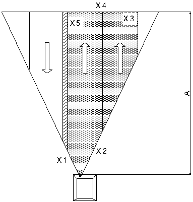
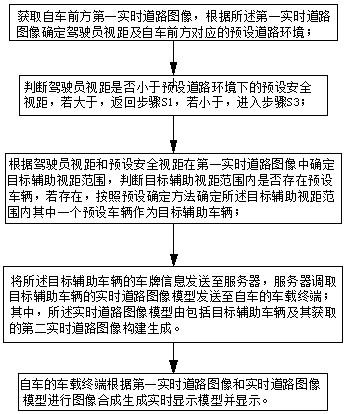
 Obviously, the specific implementation of the present invention is not limited by the above manners, as long as the method concept and technical solutions of the present invention are adopted for various insubstantial improvements. Or directly applying the concept and technical solution of the invention to other occasions without improvement shall fall within the protection scope of the present invention.

PUM

no PUM

Description & Claims & Application Information

We can also present the details of the Description, Claims and Application information to help users get a comprehensive understanding of the technical details of the patent, such as background art, summary of invention, brief description of drawings, description of embodiments, and other original content. On the other hand, users can also determine the specific scope of protection of the technology through the list of claims; as well as understand the changes in the life cycle of the technology with the presentation of the patent timeline. Login to view more.
Why Eureka
Try Eureka