
Tube-sinking cast-in-situ pile device suitable for expansive soil region and construction method

A technique for sinking cast-in-situ piles and expansive soil, which is applied in sheet pile walls, foundation structure engineering, construction, etc., can solve problems such as construction difficulties of cast-in-place piles, achieve high construction efficiency, flexible layout, and reduce impact

Inactive Publication Date: 2020-06-05
CHANGZHOU INST OF TECH
View PDF0 Cites 0 Cited by
  • Summary
  • Abstract
  • Description
  • Claims
  • Application Information

AI Technical Summary

Problems solved by technology

[0003] The present invention solves the problem of difficult construction of cast-in-situ piles in expansive soil areas in the related art, and proposes an immersed tube cast-in-place pile device suitable for expansive soil areas. By setting a plug at the bottom of the immersed tube, the foundation piles are shaped and the piles A conical cavity is formed at the end of the pile, which provides a buffer space for the expansion of the expansive soil at the pile end; a retaining ring is set within the atmospheric influence range on the pile side, and the soil inside the retaining ring is not affected by atmospheric rainfall, and the expansion force of the soil outside the retaining ring is determined by Bearing of the retaining ring, it can prevent the outer soil from expanding, shrinking and uplifting, which will have an uplifting effect on the pile body

Method used


Image

  • Tube-sinking cast-in-situ pile device suitable for expansive soil region and construction method
  • Tube-sinking cast-in-situ pile device suitable for expansive soil region and construction method
  • Tube-sinking cast-in-situ pile device suitable for expansive soil region and construction method

Examples


Embodiment 1

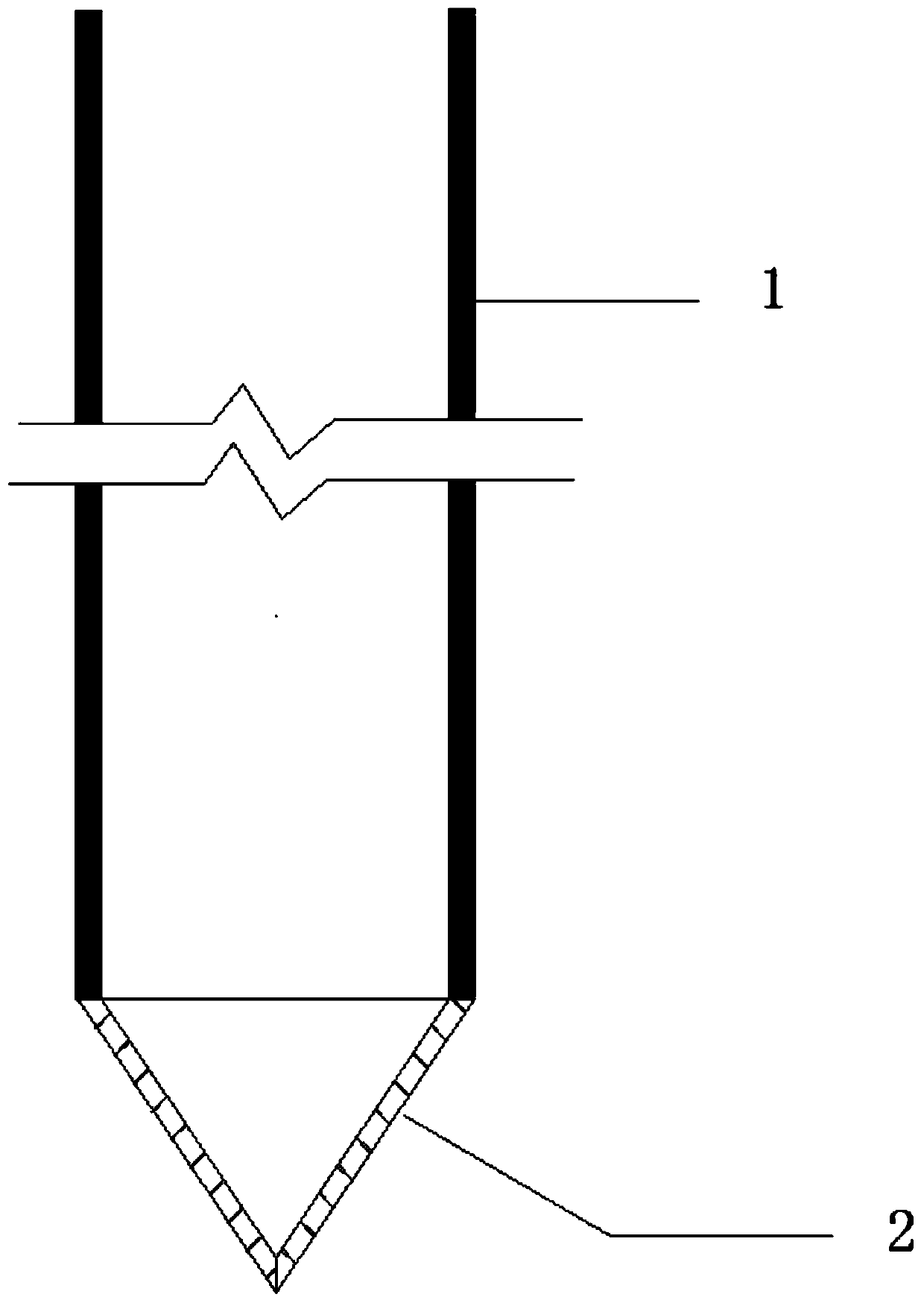
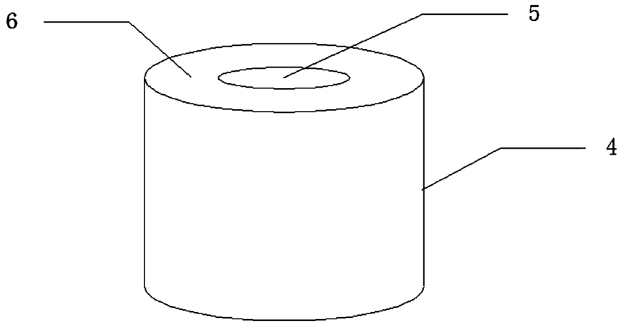
[0033] Such as Figures 1 to 6 As shown, a sinking tube cast-in-situ pile device suitable for expansive soil areas includes a valve pile tip 2, a plug 3, and a retaining ring 4, and the valve pile tip 2 is arranged at the end of the immersed tube 1; the plug 3 is A cylindrical steel block, the plug 3 is placed at the bottom of the immersed tube 1; the retaining ring 4 is a hollow cylindrical structure, the retaining ring 4 is installed on the outside of the cast-in-place pile, and the height of the retaining ring 4 is not less than the atmospheric influence depth; A cover plate 6 is welded on the top of the ring 4, and a circular opening 5 is opened on the cover plate 6, and the diameter of the circular opening 5 is not smaller than the diameter of the cast-in-situ pile.

[0034] Wherein, the materials of the immersed tube 1, the valve pile tip 2, the plug 3 and the retaining ring 4 can all be made of stainless steel.

[0035] In one embodiment, the height of the retaining ri...

Embodiment 2

[0038] Such as Figure 7-11 Shown, another aspect of the present invention also provides a kind of construction method that is applicable to the immersed pipe grouting pile of expansive soil area, comprises the following steps:

[0039] Step 1: Set the valve pile tip 2 at the end of the immersed tube 1, use the static pressure or dynamic immersed tube method for construction, and construct the immersed tube 1 to the design elevation;

[0040] Step 2: Place the plug 3 at the bottom of the immersed tube 1;

[0041] Step 3: placing steel bars 7 in the immersed tube 1, then pouring concrete to form cast-in-place piles, and then pulling out the tubes;

[0042] Step 4: After the tube is pulled out, the retaining ring 4 is sunk into the soil around the pile by static force or dynamic pile pressing.

[0043] The method can provide safety guarantee for the construction operation of the immersed pipe grouting pile in the expansive soil area, and prevent the pile body from being affect...


PUM


Abstract

The invention relates to the technical field of engineering pile construction, in particular to a tube-sinking cast-in-situ pile device suitable for an expansive soil region. The device comprises a valve pile tip, a plug and a retaining ring, wherein the valve pile tip is arranged at the end part of an sunken tube; the plug is placed at the bottom of the sunken tube; the retaining ring is mountedon the outer side of the cast-in-place pile and the height is not lower than the atmospheric influence depth; a cover plate is arranged at the top of the retaining ring and is provided with a circularopening with the diameter not smaller than that of the cast-in-situ pile. The invention also relates to a construction method, which comprises the following steps of: constructing the sunken tube toa designed elevation by adopting a static pressure or power sunken tube method; placing the plug at the bottom of the sunken tube; placing steel bars in the sunken tube, then pouring the concrete to form a cast-in-situ pile, and then pulling out the tube; and sinking the retaining ring into the soil around the pile by adopting the static or dynamic pile pressing method. By sufficiently consideringthe engineering characteristics of expansive soil, the construction efficiency is high, and arrangement is flexible, the method is suitable for cast-in-situ pile construction of various expansive soil layers, and the influence of soil expansion and shrinkage on a pile body can be greatly reduced.

Description

technical field [0001] The invention relates to the technical field of engineering pile construction, in particular to an immersed pipe grouting pile device and construction method suitable for expansive soil areas. Background technique [0002] Expansive soil is a highly plastic clay with expansive structure, multiple cracks, strong expansion and contraction, and strength attenuation. Its properties are extremely unstable, and it is a difficult soil in actual engineering, which will bring various engineering problems. The problem of expansive soil has been paid more and more attention by the engineering community, especially in the distribution area of ​​expansive soil in my country, a large number of engineering constructions have pile foundation construction. The shrinkage and swelling deformation of expansive soil will seriously affect the stress state of the pile foundation. The change of soil humidity and temperature can be used as a sign of the effect of atmospheric f...

Claims


Application Information

Patent Timeline
Patent Type & Authority Applications(China)
IPC IPC(8): E02D5/38E02D5/72E02D5/66
CPCE02D5/38E02D5/385E02D5/665E02D5/72
Inventor 李雄威
Owner CHANGZHOU INST OF TECH
Learn More