Eureka AIR delivers breakthrough ideas for toughest innovation challenges, trusted by R&D personnel around the world.

A micro-flame array burner capable of burning multi-component fuels

A multi-component, burner technology, applied in the direction of gas fuel burners, burners, combustion types, etc., can solve the problems of discontinuous temperature field, affecting the uniformity of temperature field, local high temperature, etc.

Active Publication Date: 2020-12-04
SHANDONG UNIV
View PDF11 Cites 0 Cited by
  • Summary
  • Abstract
  • Description
  • Claims
  • Application Information

AI Technical Summary

Problems solved by technology

However, the inventors have found that: this type of existing micro-flame burner can only meet the burner of burning a kind of fuel, the fuel applicability is poor, and there are limitations in actual use or production, because: (1) When the fuel type is changed, the distance between the microtubes will not change, and the shape of the formed micro-flames will change. The micro-flames may interact weakly, and the temperature field will be discontinuous, or merge to form a large flame, which will affect the uniformity of the temperature field. sex
(2) Uneven mixing of combustible gas and air will cause incomplete combustion and local high temperature, and will increase the corresponding pollutant emissions

Method used


Image

  • A micro-flame array burner capable of burning multi-component fuels
  • A micro-flame array burner capable of burning multi-component fuels
  • A micro-flame array burner capable of burning multi-component fuels

Examples


no. 1 example

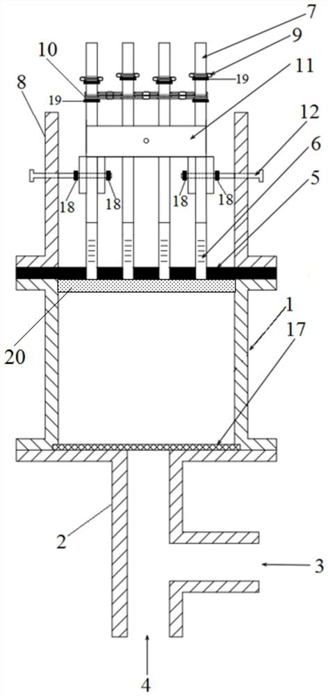
[0036] first embodiment ,refer to figure 1 , an example of a micro-flame array burner designed by the present invention capable of burning multi-component fuels, including: a gas mixing chamber 1, an air inlet pipe 2, an air inlet 3, a gas inlet 4, a microtube sealing plate 5, a hose 6. Rigid microtube 7, cylinder body 8 and microtube adjustment device; wherein:

[0037] The air inlet pipe 2 is fixed on the bottom of the gas mixing chamber 1, and the two are sealed and connected by a flange and a rubber sealing plate to avoid gas leakage. The air inlet 3 and the gas inlet 4 are respectively arranged on the intake pipe 2, and the seal of the micropipe sealing plate 5 is fixed in the upper port of the gas mixing chamber 1, so as to introduce the mixed gas and air into the rigid microtube. Tube 7.

[0038] The gas mixing chamber 1 is a pipeline swirl mixer, which is composed of a pipeline and fan blades, and the fan blades are fixed on the bottom surface of the gas mixing cha...

no. 2 example

[0046] second embodiment , further, a sintered metal plate 20 is arranged under the microtube sealing plate, which is tightly fixed on the inner wall of the gas mixing chamber 1 . The main function of the sintered metal plate 20 is flame retardancy; when the combustion velocity is lower than the flame propagation velocity (low load), the pressure in the gas mixing chamber 1 becomes smaller, or when the micropipes are blocked, a tempering phenomenon occurs, which has Security risks. After the sintered metal plate is added, when tempering occurs, the flame cannot quickly heat the cold sintered metal plate, so that the premixed gas cannot reach the combustion temperature and automatically extinguishes, blocking the flame transfer, thereby achieving the flame retardant effect.

no. 3 example

[0047] third embodiment , continue to refer to figure 1 A grid plate 17 is installed at the communicating portion of the gas mixing chamber 1 and the intake pipe 2, and when air and gas enter the gas mixing chamber 1 from the intake pipe, they can be further mixed through the dispersion of the grid plate, which contributes to Promotes an even burn.


PUM


Abstract

The invention relates to the technical field of micro flame combustors, in particular to a micro flame array combustor capable of combusting multi-component fuel. By means of the micro flame array combustor, through the characteristic that a rhombus telescopic frame can stretch and contract, right micro pipes are used as components for the joints of being connected with micro pie fixing rings in the rhombus telescopic frame at the same time (replace screws and nuts at connecting joints of a conventional rhombus telescopic frame), the distance between the micro pipes is ingeniously adjusted inthe length direction and the width direction, then the micro flame combustor can meet the requirements of fuel changes for micro pipe distance changes, and the phenomenon that due to the fact that themicro pipe distance cannot be adjusted due to fuel changes, formed micro flames are combined is avoided.

Description

technical field [0001] The invention relates to the technical field of micro-flame burners, in particular to a micro-flame array burner capable of burning multi-component fuels. Background technique [0002] The information disclosed in the Background of the Invention is only intended to increase the understanding of the general background of the invention, and is not necessarily to be taken as an acknowledgment or any form of suggestion that the information constitutes the prior art that is already known to those skilled in the art. [0003] Electric heating and flame heating are the two most common heating methods. Although electric heating has the advantages of environmental friendliness and uniform temperature, its energy utilization rate is low. In recent years, there have been many studies on direct flame heating at home and abroad, and its primary energy utilization efficiency can reach 60%. The flame used by the heater can be divided into conventional flame and micr...

Claims


Application Information

Patent Timeline
Patent Type & Authority Patents(China)
IPC IPC(8): F23D14/02F23D14/46F23D14/62F23D14/58
CPCF23D14/02F23D14/46F23D14/58F23D14/62
Inventor 许焕焕李玉昆卢林谢敏任霄汉朱子霖
Owner SHANDONG UNIV
Why Eureka
Eureka Blog
Learn More