
Electrical control system

An electrical control system and controller technology, applied in the electrical field, can solve problems such as potential safety hazards, inconvenient operation and monitoring, and difficulty in viewing the instrument readings of the control cabinet, achieving the effect of high safety

Inactive Publication Date: 2020-06-05
YULIN UNIV
View PDF8 Cites 2 Cited by
  • Summary
  • Abstract
  • Description
  • Claims
  • Application Information

AI Technical Summary

Problems solved by technology

[0002] Existing electrical control systems mostly use electrical control cabinets for centralized power supply, control, monitoring and measurement, but electrical control cabinets are generally fixed, and their operation and monitoring are inconvenient, especially in some larger electrical equipment. The monitoring function of the control cabinet cannot be taken into account during the operation, and it is difficult to observe the instrument readings on the control cabinet. At the same time, the execution visibility of the control system is poor, and the errors that occur in it cannot be fed back in time, which has great potential safety hazards

Method used


Image

  • Electrical control system
  • Electrical control system

Examples


Embodiment Construction

[0030] In order to make the objects and advantages of the present invention clearer, the present invention will be further described in detail below in conjunction with the examples. It should be understood that the specific embodiments described here are only used to explain the present invention, not to limit the present invention.

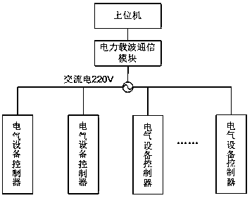
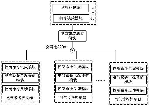
[0031] Such as Figure 1-Figure 2 As shown, the embodiment of the present invention provides an electrical control system, which is composed of a plurality of sensor nodes, a host computer, a power carrier communication module, a 220V AC power grid, and a plurality of electrical equipment controllers. The self-organizing network is connected with multiple electrical equipment controllers to form an effective internal network; the 220V AC power grid is connected with multiple electrical equipment controllers, and forms a network with the host computer through the power carrier communication module, and the sensor nodes will be The collected data...


PUM


Abstract

The invention discloses an electrical control system. The system is composed of a plurality of sensor nodes, an upper computer, a power line carrier communication module, a 220V AC power grid and a plurality of electrical equipment controllers; the sensor nodes are connected with the electrical equipment controllers in an ad-hoc network mode through Zigbee modules to form an effective Internal network; the 220V AC power grid is connected with the plurality of electrical equipment controllers; a network is formed by the power line carrier communication module and an upper computer; the sensor nodes transmit collected data to the electrical equipment controllers in a wireless mode through the Internal network, the electrical equipment controllers receive the data and instructions from the upper computer at the same time, and corresponding control instructions are output to the electrical equipment based on the data and the instructions to achieve modification of the working state of theelectrical equipment. The system has the characteristics of automation, intelligence, multiple functions, high safety and the like.

Description

technical field [0001] The invention relates to the electrical field, in particular to an electrical control system. Background technique [0002] Existing electrical control systems mostly use electrical control cabinets for centralized power supply, control, monitoring and measurement, but electrical control cabinets are generally fixed, and their operation and monitoring are inconvenient, especially in some larger electrical equipment. The monitoring function of the control cabinet cannot be taken into account during the operation, and it is difficult to observe the instrument readings on the control cabinet. At the same time, the execution visibility of the control system is poor, and the errors that occur in it cannot be fed back in time, which poses a great safety hazard. Contents of the invention [0003] In order to solve the above problems, the present invention provides an electrical control system, which connects the upper computer and multiple electrical eq...

Claims


Application Information

Patent Timeline
Patent Type & Authority Applications(China)
IPC IPC(8): G05B19/418H04B3/54H04W4/38H04W84/18
CPCG05B19/4183G05B19/4185H04B3/54H04W4/38H04W84/18Y02D30/70Y02P90/02
Inventor 冯宏伟徐绘冯宏图高莹
Owner YULIN UNIV
Learn More